These sample schematics may offer suggestions on how to use an Elithion BMS in your application.
The BMS controller is wired differently for different classes of application.
|
| EV
| HEV
| PHEV
| UPS
| Peak shaver
|
| Example
| Electric Vehicles
| Hybrid Electric Vehicles
| Plug-in Hybrid Electric Vehicles
| Uninterruptible Power Supplies
| Power grid Peak Shaver
|
| Description
| The battery is primarily charged from the grid, not from an internal source.
| The battery is charged from an internal source .
| The battery is charged either from an external source or from an internal one
| The battery is constantly kept charged from an external source
| The battery is constantly kept charged from an external source
|
| Distinct phases
| 2
| 1
| 2
| 2
| 1
|
| Source phase
| Charging from an external source, such as from the power grid, and occurs regularly, such as every night. V2G discharging is also possible.
| N.A.
| Charging is from an external source, such as from the power grid, but doesn't have to occur regularly. V2G discharging is also possible.
| Charging is from an external source, such as from the power grid, and occurs the majority of the time.
| Charging is from an external source (typically the power grid), and occurs the majority of the time. Discharging is to back to the source (typically the power grid), as requested (during times of peak demand).
|
| Load phase
| Discharging to the load (such as a motor controller) occurs when disconnected from the charging source (unplugged from the wall). Regenerative charging (regen braking) is also possible.
| Charging and discharging both from / to internal devices, such as charging from a generator and discharging to a motor controller. Charging and discharging may occur simultaneously.
| Charging and discharging are both from / to internal devices, such as charging from a generator and discharging to a motor controller. Charging and discharging may occur simultaneously.
| Discharging is to the load (such as to a local power grid) occurs when the charging source is gone (power failure).
| N.A.
|
| SOC calibration
| At the end of each full charge; remains calibrated
| Uncalibrated: SOC drifts
| Initally calibrated at the end of a full charge. If seldom charged, becomes uncalibrated: SOC drifts
| Always calibrated
| Always calibrated
|
| Capacity calibration
| At the end of each full discharge (not often: full discharge is not desirable)
| Not possible
| At the end of each full discharge (commonly happens once after each time it is fully charged)
| At the end of each full discharge (if power failure lasts long enough)
| Not normally done
|
| VS power in
| 12 V whenever plugged into the grid
| 2 V when on (e.g.: ignition is on)
| 12 V whenever plugged into the grid
| 12 V whenever the grid is OK
| 12 V all the time
|
| VL power in
| 12 V when on (e.g.: ignition is on)
| Not used
| 12 V when on (e.g.: ignition is on)
| 12 V all the time
| Not used
|
| Source current sensor
| Measures current from charger (and to inverter for V2G)
| Measures current to load (and back for regen)
| Measures current from charger (and to inverter for V2G)
| Measures current from charger
| Measures current from charger and to inverter
|
| Load current sensor
| Measures current to load (and back for regen)
| Not used
| Measures current to load (and back for regen)
| Measures current to load
| Not used
|
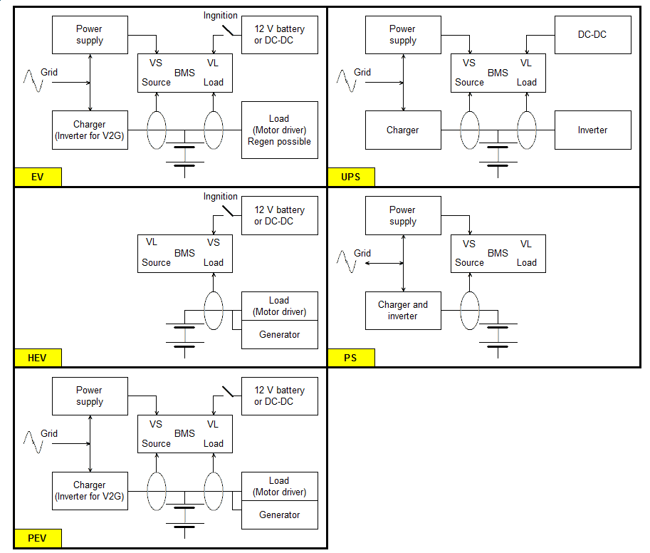
Block diagrams for each application.
In general, the Lithiumate BMS is compatible with all DC motor controllers and AC motor inverters.
The most basic way of allowing the BMS to control a motor driver is by having it drive a contactor that is connected between the battery and the motor driver.
This, however, results in a sudden loss of power when the battery is discharged, which in a vehicle is not desirable, and downright dangerous.
The better approach is a two step one:
- Make the motor controller abide to the BMS's request to reduce battery current as the battery is near depletion
- Finally, when the battery is empty, make the motor controller do an orderly shut down upon the BMS's request
There are 3 ways to reduce the motor drive as the battery is near depletion:
- Human intervention (unreliable): let the driver see a display or hear a sound controlled by the BMS, and rely on the driver to slow down the vehicle
- Step reduction: when the battery reaches a certain state of depletion, engage a low power mode, to make the driver suddenly aware of the conditions, and not allow excessive battery drain
- Gradual reduction: as the battery becomes more and more depleted, gradually reduce the battery current that the motor driver is able to use
Very few motor drivers have the provisions to enable such control.
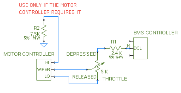
In most cases, the way to let the BMS control the motor driver is by reducing the range of the throttle pot, electrically:
- For step control, let the BMS control the addition of a resistor across a 2-wire pot when the battery is nearly empty.
- For gradual control, power a 3-wire throttle pot from the DCL ouput, which is normally at 5 V, but is reduced at the end of the battery charge.
The most basic way of allowing the BMS to control a charger is with an AC relay on the charger's input, driven by the HLIM output of the BMS.
The HLIM output polarity must be set so that the HLIM is normally grounded.
This method works with any charger.
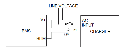
BMS controls charger through a relay's NO contacts.
The relay must have the following specifications:
- Coil voltage: DC rated, equal to the available supply voltage, which must not exceed the BMS controller's Absolute maximum ratings
- Coil resistance: such that the resulting current does not exceed the BMS controller's Absolute maximum ratings
- Contact voltage rating: AC rated for the AC line voltage
- Contact current rating: rated for carrying and braking the maximum input AC current of the charger at full power
- Regulatory rating: for the location of its use
You must decide which relay works in your application.
Questions to ask are:
- The load that the charger will place on the line supply: resistive or inductive? start up current? continuous current? voltage range? does it have a control input with which you will shut it down before you turn off the AC power?
- How you want to mount the relay: soldered? socket? PCB? surface mount? chassis mount? DIN rail mount?
- What kind of environment the relay will be in: dry? wet? spray? any corrosive gases? ambient temperature range? any unusual atmospheric pressure?
- What supply voltage is available to drive the relay: 12 Vdc? 24 Vdc? 48 Vdc?
- Where will the system be used: what local and national regulations must it meet?
Only after those questions are answered can an appropriate relay be recommended.
As you can see, there are hundreds of permutations.
We are not able to offer suggestions for all those permutations.
Here is just one example, with a system with the following specifications:
- 12 V supply
- 115 Vac line voltage
- 1500 W Power Factor Corrected charger
- Used in the US
- Automotive environment, in the passenger cabin
Then the requirements for the relay are:
- Coil voltage: 12 Vdc
- Coil resistance: >= 10 Ohm
- Contact voltage rating: 125 Vac rated
- Contact current rating: 15 Aac resistive load, carrying, braking
- Regulatory rating: UL
- -40 to +85 °C
- Sealed not necessary
WARNING The suggestions below are for the particular example system described above; they are believed to be correct, but not guaranteed to be so.
Examples of parts that will meet those ratings include:
- Panasonic HL1-H-DC12V-F, socket mounted relay, 20 SPDT, 125 Vac 15 Aac
- Tyco T9AP5D52-12, chassis mounted relay, SPDT, 240 Vac, 20 Aac
- TT Electronics OSSRD0002A, chassis mounted solid state relay, SPST-NO, 250 Vac, 15 Aac
Many other methods of connecting a charger to the BMS exist, based on the specifications of the charger and the user's preference.
Here are six examples, which emphasize the method to power the BMS whenever the AC source is present, even during those times that the BMS is turning off the charger.
They all show a single pole relay. You may replace the relay with an SSR (Solid State Relay). In some cases a 2 pole relay would be required.
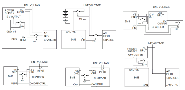
Examples of connecting the BMS to the charger.
Note that powering the BMS directly from a standard power supply will result in the BMS forgetting the SOC when powered down.
That is because the 12 V supply must drop faster than 10 ms, or the BMS controller doesn't realize that the power is going away, and doesn't store the SOC.
So, either the power supply must have a very small output capacitor, or you need to add a relay between the supply and the BMS controller, whose coil is powered by the supply, to make the voltage drop suddenly.
The first and last example above use a a power supply to power the BMS whenever plugged in for charging.
The requirements for such a supply are:
- Input voltage same as all possible AC input voltages; for example, a 90 Vac to 265 Vac switching supply can handle both 110 and 220 V line inputs
- 12 Vdc output
- At least 150 mA out
For example, this universal input, 12 V output, switching power supply meets the above requirements: ST Micro's SPAC265BC12P0.30
WARNING These are just examples. You must decide what circuit is appropriate in your application.
For electric vehicles, it is best to warn the driver as the battery gets low, before totally shutting down the drive.
One way of doing so is to reduce the range of the throttle gradually as the battery nears the end of its charge.
For a 3-wire throttle, this can be done by wiring one of the leads to the BMS controller instead of to the motor controller.
The resistor values may have to be changed to match the voltages at the 2 ends of the throttle pot when it's connected normally to the motor controller.
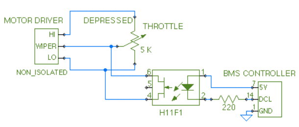
If the throttle input of the motor driver is not isolated (e.g.: Curtis Instruments) you can use this circuit to isolate the DCL output of the BMS from the throttle.
The H11F1 FET optoisolator behaves like a variable resistor: its resistance decreases as more current flows through the LED.
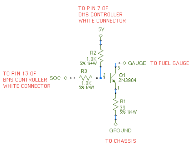
For EV conversions, you may be able to have the BMS controller drive the vehicle's fuel gauge directly.
- The BMS controller has an SOC output
- Many vehicles have a fuel gauge that is connected to 12 V at one end, and through a resistive sensor ("sender") in the fuel tank, to ground
Gauge:
- 127 Ohm
- 90 mA to show full
- 35 mA to show empty
Sender:
- 4 Ohm when full
- 107 Ohm when empty
BMS controller's SOC output (Control connector, pin 15):
- 5 V when full
- 0 V when empty
You can use this circuit to adapt between the two.
- Sample schematic 1 (pdf):
- CAN bus, but analog throttle
- Battery: 72S1P Li-Ion cells in 6 banks; 12 V aux battery
- charger: Brusa NLG5
- Motor: Azure DMOC motor inverter and AC motor (included contactors
- RM Michaelides RM1001 CAN display
- Small DC fan, cable mounted current sensor, loss of isolation test