
The Elithion BMS is compatible with a Manzanita Micro charger with the addition of some hardware.
Manzanita Micro PFC manual, same as original, only MUCH smaller file size (400 kb i/o 3.7 MB) (pdf)
The charger is controlled through its RegBus connector.
It is intended for use with Manzanita Micro's MKII regulators.
It can be used to control the charger's operation.
By the way, "Bus" is spelled with only one 's', regardless of how it is spelled in the manual and on the front panel.
The Modular RJ25 connector has 6 positions, 6 contacts.
Holding the connector in your hand tab side down with the cable opening toward you, the pins are numbered 1-6, left to right.
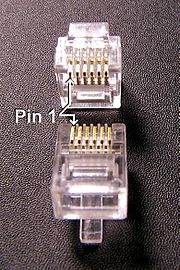
RJ25 connector
In many places the RJ25 connector is incorrectly called "RJ11".
If it has 6 contacts, they may call it RJ11 but it's really an RJ25.
| Ckt #
| Color
| Old rev function
| Present rev function
|
| 1
| White or orange
| +5 volts output
- From 78L05 in charger
- Referenced to line voltage
|
| 2
| Black
| Hot reg input
- This line has a pull-down to ground inside the charger
- The hottest MKII regulator pulls up the voltage on this wire
- Pulling this line to the +5 V (pin 1) shuts down the charger
|
| 3
| Red
| Voltage control input
- On charge: external device may pull this line low to set regulator threshold up 10% (15.0 to 16.5 typical)
- On discharge: external device may pull this line low to indicated a battery has gone under the UV setpoint
| Low batt active low
|
| 4
| Green
| Common reference
- Referenced to line voltage: DO NOT connect to earth ground
|
| 5
| Yellow
| Cold reg input
- This line has a pull-up to +5V inside the charger
- The coldest MKII regulator pulls down the voltage on this wire
| EvilBus negative
- Digital communication for the Mark 3 Digital Regulators
|
| 6
| Blue
| Not used
| EvilBus positive
- Digital communication for the Mark 3 Digital Regulators
|
The colors above are standard. It seems that Manzanita Micro reverses the color order from the standards.
To turn off the charger, connect together pins 2 and 1 of the RegBus connector (Hot reg to + 5 V)
The best way of allowing the BMS to conytrol the charger is through a standard DC relay:
- Physically, locate it close to the charger
- Change the default polarity for the HLIM output to: open when the battery is full
- Connect the COM and NC contacts of the relay to pins 1 and 2, in either order
- Connect the coil of the relay to to the the V+ (or Vs) line and to the HLIM output
Interfacing the Manzanita Micro PFC charger and the Elithion BMS
You may consider the following parts, but you are responsible for selecting the appropriate parts for your application:
Manzanita Micro PFC wiring (pdf)
The charger does not have an output to indicate the battery current. Therefore, a current sensor is required. There are 2 options:
- Use the same current sensor as for the load current:
- Recommended only if that current sensor's range is 100 A or less (the errors introduced by a high current sensor are excessive, and will result in incorrect State Of Charge calculation: a 600 A sensor can be off by 6 A)
- The current sensor must be placed on a line that carries both the load current and the charger current.
- Use a dedicated current sensor just for the charging current
- Recommended if the load current can be 100 A or more
- This current sensor should be placed on a line that carries only the charger current, for 2 reasons:
- The load current, if much higher, may saturate the this current sensor, and may slightly damage it
- In cases where the charger and the load can be on at the same time, the BMS controller will read the load current twice, once from each sensor, and report twice the current
Connections to the controller
- A current sensor can be powered by the BMS controller:
- If 5 V, it can be powered by the Control connector's +5 V and Signal Ground lines
- If 12 V, it can be powered by the Control connector's V+ and Signal Ground lines
- If +/- 15V, it can be powered by the External Current Sensor connector's +15V, -15V and Ground lines
- Its output goes to the controller
Some have reported that their Manzanita Micro charger did not stop charging even though it had been commanded to stop (through the RegBus).
If that is a concern, you may want to add a failsafe circuit.
A contactor on the DC output is not an option, because Manzanita Micro states that that could damage the charger.
So, a contactor on the AC input is the only option.
- Wire the contactor's contacts in series with the AC input
- Wire the contactor's coil
- For low power 12 V contactors, connect it to the FLT output and the V+ (or Vs) line
- For high power 12 V contactors, or for AC coil contactors, use an intermediate 12 Vdc relay
- Toggle the polarity of the FLT line
- If the charger should not stop when told, a fault will occur some time later, and open the contactor
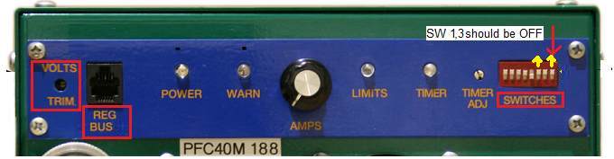
The charger must be adjusted as follows:
- DIP switch 1, 2 and 3 (closest to the edge of the box): OFF (Away from the "SWITCHES" label)
- This turns off the timer function
- (The timer function is useful to prevent thermal runaway in lead-acid batteries, and systems without a BMS)
- "VOLTS TRIM": set so that, when the pack is full and balanced, the charging current is reduced to 0
- Leave this adjustment up
- Allow the pack to be fully charged, and wait for it to become fully balanced
- Wait fot the next time the charger starts charging again
- Start turning this adjustment down (counter-clockwise) until the current starts dropping
- Carefully adjust it a bit lower, until the current just goes down to 0
Manzanita Micro PFC charger settings
The BMS turns the charger off and on during balancing.
The problem with using the settings that Manzanita Micro insists on is that, if you do, once the BMS turns off the charger, it may not be able to turn it on again.
That is because of the Time-out function, and because of the Low-Voltage function:
- The Time-out function prevents the charger from coming back on if it has been turned off for some time (though DIP switch 8 should overcome this).
- The Low-Voltage function prevents the charger from coming back on if the battery voltage is still above a set, Low-Voltage point
Therefore, you need to turn Off DIP switch 1 to disable the Timer function, and allow the BMS to cycle the charger off and on.
- Start charging
- Check that there is charging current
- Disable charging
- Home / Test / Force outputs / HLIM / N
- Check that there is no charging current
- Re-enable charging
- Home / Test / Release outputs
- Check that there is charging current
Charger doesn't charge, even though BMS says that charging is OK
- Disconnect the RegBUS connector from the charger
- If charging starts:
- Check that there is no voltage on the input of the opto-isolator (with resistor) / relay / solid-state relay
- If there's voltage, check the HLIM polarity: Home / Set-up / Charge Limits / HLIM output polarity: should be "No"
- Check that there isn't short circuit on the output of the opto-isolator / relay / solid-state relay
- If charging doesn't start:
- Check the adjustments of the charger, especially the CURRENT adjustment and the voltage trimmer
- See if turning the charger's circuit breaker off and on fixes the problem
Charger doesn't turn off when BMS's HLIM line is tripped.
- Check that there is 12 V (or so) on the input of the opto-isolator (with resistor) / relay / solid-state relay
- Check the lines from the BMS controller to the opto-isolator / relay / solid-state relay
- If there's no voltage, check the HLIM polarity: Home / Set-up / Charge Limits / HLIM output polarity: should be "No"
- Check that there is a short circuit on the output of the opto-isolator / relay / solid-state relay
- Check the lines from the opto-isolator / relay / solid-state relay to the RegBUS connector