|
|
index  reference test_fixtures cellboard_test_fixture reference test_fixtures cellboard_test_fixture
Cell board test fixture
Description and construction of a test fixture for cell boards for a Lithiumate™ BMS

- The board tests itself, with the help of a very simple test fixture
- The code for it is programmed in every board and runs once every time it is powered-up,
- In normal operation, in actual use:
- The test fails right away, and therefore the LED blinks 2 times (repeated 3 times)
- Then it runs the regular code
- In a test fixture:
- The test proceeds, and the LED blinks once (if it passes) or n times (repeated 3 times) if it fails
The test fixture consists of:
- A power supply
- A test fixture electronics board
- A test fixture head that mates to the Device Under Test (DUT) with test pins
- The fixture head mates to the B+, C+, C- and B- pads in the DUT
- The test fixture does the following:
- The fixture powers the DUT with a fixed 3.0 V voltage through its B+ and B- pads
- There is a resistor on that line, so that, if the DUT load resistor is on, the voltage drops below 3.0 V
- The fixture routes the current out of the C- pad back into the C+ pad
- At initial power-up, the test fixture applies a short pulse of current to the C- input, to get things started
- The fixture includes:
- A push-button switch to run the test
- Additional parts to test the positive and negative end boards
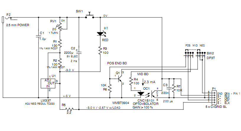
Cell Board test fixture schematic. Board (top) complete fixture (bottom).
- The wall-mounted power supply generates 5 Vdc, unregulated
- The internal regulator generates exactly 3.0 V (adjustable with a trimmer)
- The supply feeds a large capacitor through a resistor, so that its unloaded voltage is 3.0 V, but when loaded with 18 ohms (on the Cell Board), it drops to 2.67 V
- A push-button switch applies that voltage to the Cell Board; an LED lights up to indicate that there's power
- The fixture routes the Cell Board's output current back to the input, in ways that depend on the type of Cell Board:
- Mid-bank Cell Boards:
- The slide switch is flipped to the "Mid" position, enabling the normal current path through the opto-isolator on the test fixture
- The test fixture head 'C+' and 'C-' test pins are both used
- The current from the 'C-' pad is routed through a slide switch, an opto-isolator (with a gain > 100 %) to the 'C+' pad
- Positive end Cell Boards:
- The slide switch is flipped to the "End" position, disabling the normal current path through the opto-isolator on the test fixture
- The test fixture head 'C-' test pin is used, but the 'C+' is not
- The Cell Board already includes an opto-isolator on the input, across the 2-pin TX connector (or pads)
- A pigtail from the test fixture is plugged into the TX connector (or pads)
- The Cell Board's output current is routed from the 'C-' pad, through the slide switch, amplified by a transistor, routed through the pigtail, to the RX connector (or pads), to that opto-isolator input
- Negative end Cell Boards:
- The slide switch is flipped to the "End" position, disabling the normal current path through the opto-isolator on the test fixture
- The test fixture head 'C+' test pin is used, but the 'C-' is not
- The Cell Board already includes an opto-isolator on the output, across the 2-pin RX connector (or pads)
- A pigtail from the test fixture is plugged into the RX connector (or pads)
- The pigtail picks-up the opto-isolator output on the Cell Board, and feeds it directly back to the 'C+' pad of the Cell board
- In all 3 cases, the gain is greater than 100%, so that the current is latched on
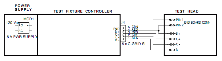
The power supply is an unregulated wall-mounted, 5 V supply.
BOM:
1 5 Vdc, 250 mA Wall wart MOD1
The test fixture head is built using 2 blank Cell Board PCBs, separated by 0.315 inch standoffs.
The four pads ('B+', 'C+', 'C-' and 'B-') are drilled to fit spring loaded test pins.
The test pins' sockets are soldered in place.
A 4-wire pig tail is connected to all four test pins, and has a 4-pin connector at the other end for the test fixture board
BOM:
2	Cell Board	PCBs	PCB1-2
4	PIN	PIN	TERM	T1-4
1	4 x C-GRID SL	FEMALE	CON	J1
1	24 AWG black	wire	W1
1	24 AWG red	wire	W2
1	24 AWG orange	wire	W3
1	24 AWG gray	wire	W4
4	4-40 x 3/8"	M-F standoffs	ST1-4
2	4-40 x 1/2"	set screw
2	4-40 x 3/8"	F-F Nylon standoffs ST5-6
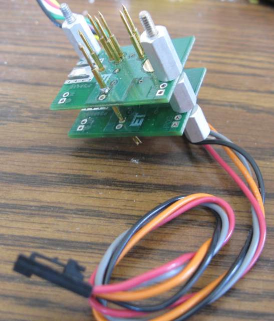
Example of test fixture head
The test fixture board is built on a piece of perf-board.
BOM:
1	perf-board	PCB	PCB1
1	1.0uF	50V X7R MONO	CAP	C1
1	1000uF	5V ELEC	CAP	C2
1	100n	50V X7R MONO 0805	CAP	C3
2	2 x C-GRID SL	FEMALE	CON	J2-3
1	LM337	ADJ NEG REGUL TO220	IC	U1
1	4 x C-GRID SL	MALE PCB HDR STR GLD	CON	P1
1	CNC1S101	OPTO-ISOLATOR	OPTO-ISO	OC1
1	RED	TINTED DIFF T1-3/4	LED	H1
2	130	1% 1/4W	RES	R1-2
1	2.2	5% 1/10W 0805	RES	R5
2	100	5% 1/10W 0805	RES	R3-4
1	20	1 TURN	RTRIM	RV1
1	SPDT	SLIDE STRAIGHT 0.1 inch	SW	SW2
1	N.O.	PUSHBUTTON	SW	SW1
1	MMBT3904	40V,  .2A, .6W, NPN	XSTR	Q3
The cell board performs the following tests, in order:
During the bus test, the following occurs:
- When the test fixture push-button is first pressed, the fixture puts a short pulse of current into the 'C+' pad
- The current goes through the DUT and out of the 'C-' pad, and back into the test fixture
- The test fixture amplifies that current, and feeds it back to the 'C+' pad, therefore completing a loop, and the current continues uninterrupted
- After 1.6 ms, the test program in the DUT block the current out of the 'C-' pad, and the pulse ends
The voltage at the C- input is a pulse, 3 V high, whose shape and duration depends on whether the cell board is working properly.
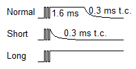
Pulse on 'C-' on Cell Board test fixture: normal (top), short (middle) and long (bottom)
Normally:
- Starts with about 250 us of switch bounce
- then 1.6 ms total pulse length, at which point the DUT stops the current out of C- by shorting the base and emitter of Qout
- then a 330 us TC decay tail
Short pulse, if there's no feedback current from C+ to C-:
- Starts with about 250 us of switch bounce
- then a 330 us TC decay tail
Long pulse, if the cell board in unable to stop the current out of C-:
- Starts with about 250 us of switch bounce
- Remains high
The cell board test program does the following:
- Waits 100 us
- If the pulse has already ended, it reports a "Short Pulse" error: 2 blinks
- Forces off the current out of the 'C-' pad
- Waits another 300 us
- If the pulse doesn't end, it reports a "Long Pulse" error: 3 blinks
The Cell Board Program measures and checks the temperature reading.
The reading cannot be checked accurately, because the room temperature is not known.
It does the following:
- It measures the reading of the on-board thermsitor
- If the reading is very low, it reports a "Temperature = 0" error: 4 blinks
- If the reading is low, it reports a "Reads hot" error: 5 blinks
- If the reading is high, it reports a "Reads cold" error: 6 blinks
- If the reading is very high, it reports a "Temperature = FFh" error: 7 blinks
The Cell Board Program measures and checks the voltage reading.
The reading can be checked accurately, because the supply voltage is known: 3.0 V.
It does the following:
- It measures the reading of the on-board voltage sensor
- If the reading is very low, it reports a "Ref reading = 00h" error: 8 blinks
- If the reading is low, it reports a "Ref reading too low" error: 9 blinks
- If the reading is high, it reports a "Ref reading too high" error: 10 blinks
- If the reading is very high, it reports a "Ref reading = FFh" error: 11 blinks
The Cell Board software turn on the balancing load, which will drag the test fixture supply voltage down, because it includes a resistor in series.
It does the following:
- It turns on the load
- If waits 10 ms
- If the supply voltage hasn't dropped, it reports a "No load" error: 12 blinks
If the Cell Board software reaches this point without errors, the Cell Board passes the test: it reports "Pass": 1 blink
The test fixture can be used to test loose cell boards (that are not installed on cells).
Testing must be done at room temperature, or "too cold" or "too hot" failures will result.
- Power up the test fixture
- Connect the cell board to the test fixture (if multiple sections, connect just one of the sections)
- Press the test fixture's push button
- Note the behavior of the LED on the cell board, and use the table below to troubleshoot
| LED
| Result
| Problem
| Cause
| Possible components
|
| 1 blink
| Pass
|
|
|
|
| 2 blinks
| Fail
| Input pulse too short
| no feedback from C- to C+
| Micro pin 3 shorted, Rbus open, Qout bad/bridged, test fixture C- pin
|
| 3 blinks
| Fail
| Input pulse doesn't end
| Unable to ground ouput
| Micro pin 3 open, Qout bad/bridged, C+ shorted to B+, C- shorted to B-
|
| 4 blinks
| Fail
| Temperature = 0
| No Therm reading
| Thermistor shorted
Rtherm open/missing
Micro pin 7 open/bridged to pin 8
Open trace
|
| 5 blinks
| Fail
| Reads hot
| Therm reading is low
| Too hot in the room
Bad thermistor
Rtherm value too high
|
| 6 blinks
| Fail
| Reads cold
| Therm reading is high
| Too cold in the room
Bad thermistor
Rtherm value too low
|
| 7 blinks
| Fail
| Temperature = FFh
| No Thermistor
| Thermistor missing/open
Rtherm bridged
Micro pin 7 open
open trace
|
| 8 blinks
| Fail
| Ref reading = 0
| No Vref input
| Uref bad/bridged, R4 open/missing, open trace
|
| 9 blinks
| Fail
| Ref reading too low
| Vref reading is low
| Micro pin 5 and 6 bridged, open trace
|
| 10 blinks
| Fail
| Ref reading too high
| Vref reading is high
| Micro pin 5 open
|
| 11 blinks
| Fail
| Ref reading = FFh
| No Vref
| Uref missing/open/bad, open trace
|
| 12 blinks
| Fail
| No load
| Load doesn't come on
| MOSFET missing/open/bad, Rload open, open trace
|
| Off
| Fail
| No input pulse
| Doesn't see fixture
| Not programmed
Ferrite missing / unsoldered
R-LED missing / unsoldered
LED missing / backwards / bad / unsoldered
Micro missing / unsoldered
MOSFET missing / unsoldered
Rin open
Cin shorted
pin 4 open
trace
test fixture C+ pin
|
| Always on
| Fail
| Load on
| Load drive always on
| MOSFET shorted/bridged
|
An extended test includes measuring the current into and out of the cell board.
Hardware:
- Add a Digital Voltmeter (DVM) in series with the C- line, set to measure µA
- Add a second DVM in series with the B+ line, set to measure µA
- Add a normally closed push-button switch across that second DVM, to bypass the B+ current around the DVM
Procedure:
- Connect the B+, B- and C- lines to the cell board; do not connect the C+ line
- Turn on the test fixture
- Note that the cell board shows two flashes
- Note that the current out of the C- line is less than 5 µA (typically less than 0.3 µA)
- Turn off the test fixture
- Connect the C+ line to the cell board
- Turn on the test fixture
- Note that the cell board shows one flash, 3 times
- After the 3rd flash wait 2 more seconds
- Push the switch across the B+ meter, so that current flows through the meter
- Note that the current into the B+ is less than 10 µA (typically about 1.7 µA)
- Release the switch across the B+ meter
- Turn off the test fixture
- Disconnect the cell board

|
|