Do not allow conductive objects (tools, solder...) to come into contact with cells or Cell Board
Do not touch more than one battery connection at the same time
Good technique
Unfortunately, we do not have the resources to teach all of our clients proper assembly procedures, which are essential for a succesful project.
What we can do is pass along this info to you:
Prepare a Cell Board for each cell in series in that bank
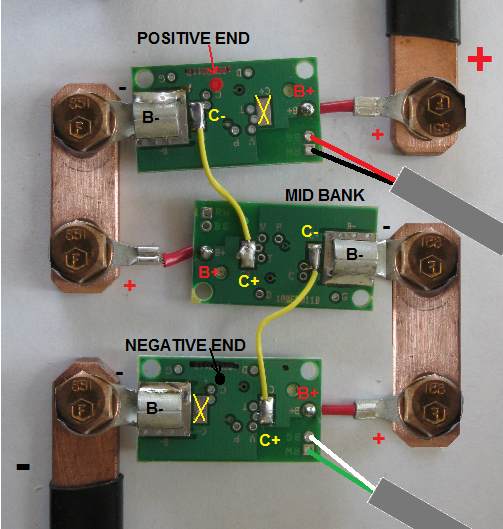
Prepare 1 Positive End Cell Board for the most positive cell in the bank
Prepare 1 Negative End Cell Board for the most negative cell in the bank
Prepare n-2 mid-bank Cell Boards for the the rest of the cells in the bank, where n is the number of cells in series in the bank
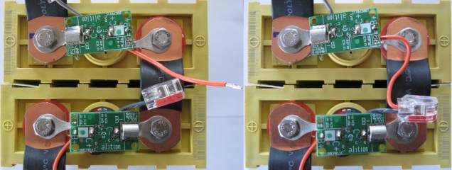
Orient the Cell Board properly DO NOT CONNECT BACKWARDS!
The ring terminal that is mounted directly to the Cell Board (labeled 'B-' on the PCB) goes to the negative terminal
The ring terminal that is mounted on a red wire (labeled 'B+' on the PCB) goes to the positive terminal
The electronic components go towards the cell, the LED towards you
Place a Cell Board on the negative terminal of its cell
Remove the bolt from the cell's negative terminal, keeping the power connection in place
Place the 'B-' ring terminal (mounted directly to the Cell Board) on top of the power connection on the negative terminal
Put the bolt back in and secure it
Connect the Cell Board to the positive terminal
Touch that terminal with the 'B+' ring terminal (mounted on the red wire)
The LED will blink twice, and do so 3 times in a row
If the LED doesn't blink when first connected, DISCONNECT THE CELL BOARD IMMEDIATELY
If you installed the board backwards and removed it immediately, once connected properly it may appear to work correctly; however, it may be damaged and drain its cell
Test a Cell Board with a current meter in series with one of its power terminals; after the blinking stops there should be no measurable current drain
If the Cell Board draws measurable current after the blinking stops, or if it reports the wrong voltage, the Cell Board is damaged: replace it
If the Cell Board was connected properly, and yet the LED doesn't blink, please see the cell troubleshooting page
Remove the bolt from a cell's positive terminal, keeping the power connection in place
Place the 'B+' ring terminal (mounted on the red wire) on top of the power connection on the positive terminal
Put the bolt back in and secure it
Repeat with the other cells in a bank
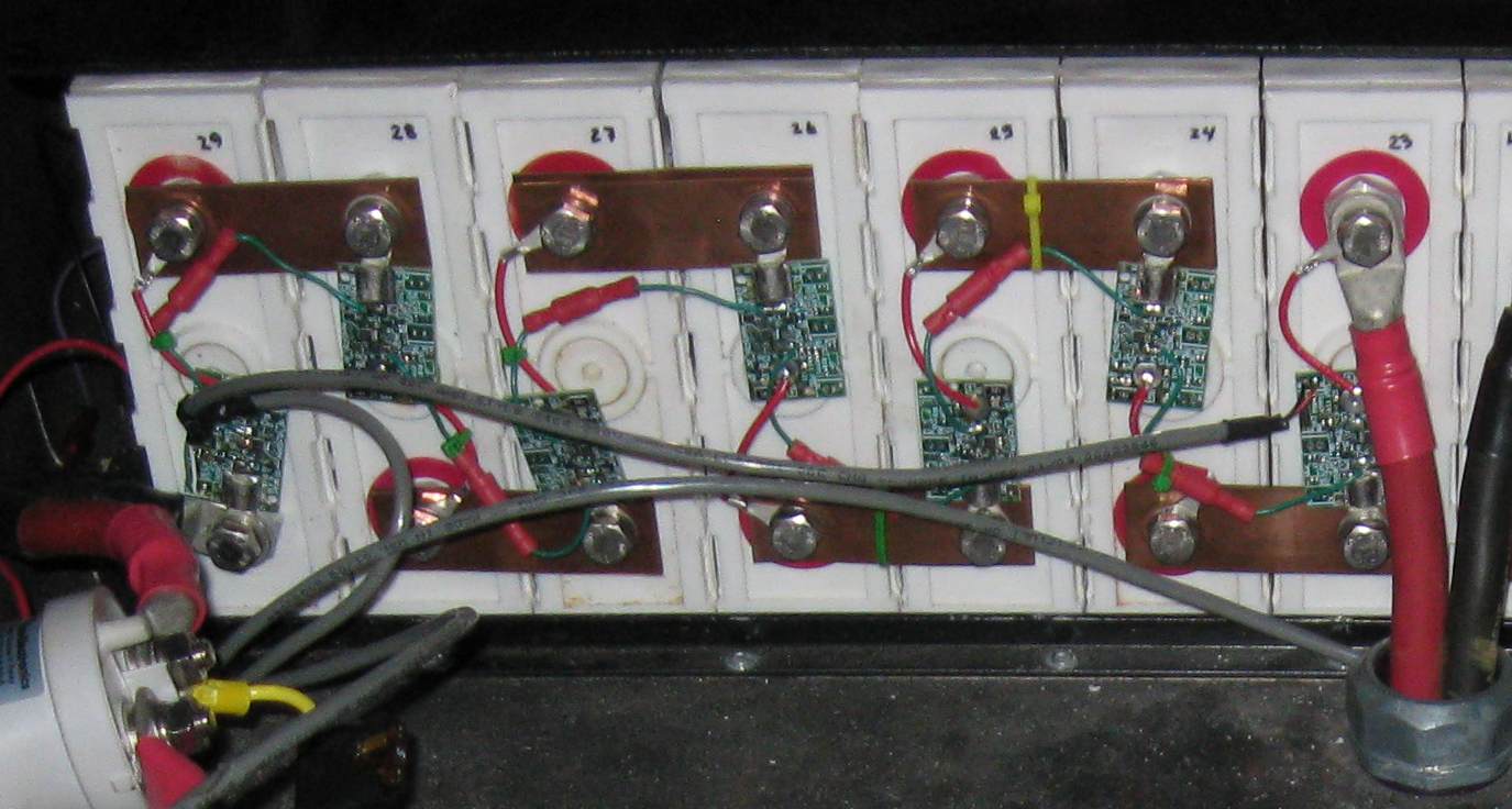
Cell Board communication wires installation
Rev C Cell Boards
In between each pair of adjacent Cell Boards, the orange wire from the most negative of the 2 Cell Boards is connected to the splice at the end of the gray wire from the most postive of the 2 Cell Boards.
Point the gray wire towards the negative terminal of the cell
Route the orange wire along the power bus bar between cells, and then to the gray wire in the adjacent Cell Board
If the orange wire is too long, cut it shorter, so that it ends at the splice on the gray wire
Strip the end of the orange wire 0.4" (1 cm)
Insert the orange wire in an open slot in the splice at the end of the gray wire, push all the way in
If required, secure the orange wire in place (use wire ties; do not twist it around the red wire or the bus bar)
In particularly noisy installations, you may need to use shielded cable; Before using this solution, first follow the noise abatement procedures, which usually are sufficient to eliminate problems due to noise pick-up, without the need for shielded cable
Cut and strip orange wire (left) and instert in splice (right).
Rev B Cell Boards
Measure and cut lengths of yellow wire to connect adjacent Cell Boards
If longer than 2" (50 mm), route it along the red power wire, along the power bus bar, and then to the adjacent Cell Board, securing it in place (do not twist it around the red wire and the bus bar: use wire ties instead)
In particularly noisy installations, you may need to use shielded cable; Before using this solution, first follow the noise abatement procedures, which usually are sufficient to eliminate problems due to noise pick-up, without the need for shielded cable
Strip each end of the yellow wire 1/4" (6 mm)
Tin the ends of the yellow wires
Tin the 'C-' and 'C+' pads on the Cell Boards, except for the 'C+' pad in the Positive End Cell Board, and the 'C-' pad in the Negative End Cell Board, and the
Use a yellow wire to connect the 'C-' pad in the Positive End Cell Board to the 'C+' pad in the following (more negative) Cell Board
Use a yellow wire to connect the 'C-' pad in the that second Cell Board to the 'C+' pad in the following (more negative) Cell Board
Etc.
Use a yellow wire to connect the 'C-' pad in the next to last Cell Board to the 'C+' pad in the Negative End Cell Board
