|
|
index  install install_cell_board_small_cyl_single install install_cell_board_small_cyl_single
Install - single small cylindrical cell board
Installation and wiring instructions for cell boards for single, small cylindrical cells

A cell board WILL be damaged if you do any of these common mistakes.
A DAMAGED CELL BOARD MAY DRAIN ITS CELL!
 Li-Ion batteries are dangerous!
- Wear safety glasses.
- Do not allow conductive objects (tools, solder...) to come into contact with cells or Cell Board
- Do not touch more than one battery connection at the same time
Unfortunately, we do not have the resources to teach all of our clients proper assembly procedures, which are essential for a succesful project.
What we can do is to pass along this info to you:
It is assumed that:
- Cells are already joined together into a battery ("naked battery")
- Preferably, the cells are glued together to form a single, mechanically stable block
- Contact plates are already welded to the cells
- Contact plates include tabs that extend past the edge of the cells, for connection to the Cell Board
- Tabs are about 0.2" wide and extend about x 0.2" past the edge of the cells (5 x 5 mm)
- For each set of cells in parallel, one cell has 2 tabs, one at each end
- Tabs centerlines are lined-up with each-other
Naked battery, ready for a Cell Board
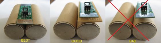
Do not place cell board directly on top of the cell: connector pins will pierce the cell's coating.
- Preferably, rotate the naked battery upright, so that the tabs at the end of the contact plates are accessible
- Identify a bank of cells: see the banking page
- Prepare a Cell Board for each cell in series in that bank
- Prepare 1 Positive End Cell Board (red color dot) for the most positive cell in the bank
- Prepare 1 Negative End Cell Board (black color dot) for the most negative cell in the bank
- Prepare n-2 mid-bank Cell Boards (green color dot) for the the rest of the cell in the bank, where n is the number of cells in series in the bank
- Place a Cell Board against its cell, with the electronic components facing towards the cells (nested in the space between cells), and oriented for the proper polarity:
- DO NOT CONNECT BACKWARDS!
- Pad on Cell Board labeled 'B+' is located by the positive tab
- Pad on Cell Board labeled 'B-' is located by the negative tab
- Fold and solder the tabs down against the Cell Board
- Solder the tabs to the pads
- Once both tabs are connected, the LED will blink twice, repeated a total of 3 times
Battery with single Cell Board
Side-by-side cell arrangement
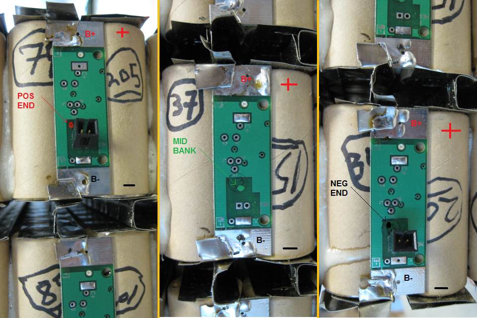
Single Cell Boards mounted on cells:
columnar cell arrangement
positive end (left, red dot); mid-bank (center, green dot); negative end (right, black dot)
- Measure and cut lengths of yellow wire to connect adjacent Cell Boards; If longer than 2" (50 mm) you may need to use shielded cable
- Strip each end of the yellow wire 1/4" (6 mm)
- Tin the ends of the yellow wires
- Tin the 'C-' and 'C+' pads on the Cell Boards, except for the 'C+' pad in the Positive End Cell Board, and the 'C-' pad in the Negative End Cell Board, and the
- Use a yellow wire to connect the 'C-' pad in the Positive End Cell Board to the 'C+' pad in the following (more negative) Cell Board
- Use a yellow wire to connect the 'C-' pad in the that second Cell Board to the 'C+' pad in the following (more negative) Cell Board
- Etc.
- Use a yellow wire to connect the 'C-' pad in the next to last Cell Board to the 'C+' pad in the Negative End Cell Board
Communication wire between Cell Boards
Side-by-side cell arrangement
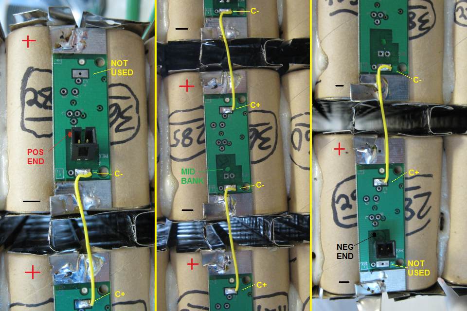
Single Cell Boards wired together:
columnar cell arrangement
positive end (left, red dot); mid-bank (center, green dot); negative end (right, black dot)
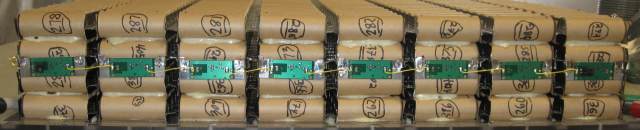
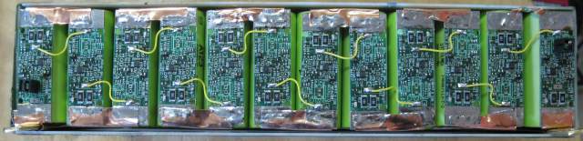
Complete bank, 8 cells in series, columnar cell arrangement (top) and side-by-side arrangement (bottom)
If the end cell boards do not have connectors, you will have to solder the communication cables to the BMS controller directly to the positive and negative end cell boards.
- Install the batteries and the controller in their final positions in the battery pack
- Prepare the communication harness for this bank
- Plug the communication harness to the controller in one of the 'BANK' sockets:
- Start from the socket labeled 'BANK 0', the use the next available socket: 'BANK 1', 'BANK 2', etc
- If using multiple batteries in parallel, see the banking page
- Connect the communication harness to the Cell Boards in that bank:
- If using plugs:
- Plug the connector with red and black wires to the plug marked 'C+', on the Positive End Cell Board
- Plug the connector with white and green wires to the plug marked 'C-', on the Negative End Cell Board
- If not using plugs:
- Solder the end with red and black wires to the pads marked 'C+', on the Positive End Cell Board: red to the round pad, black to the square pad
- Solder the end with white and green wires to the pads marked 'C-', on the Negative End Cell Board: white to the round pad, green to the square pad
Communication cables added in
Repeat with the remaining banks

|
|