You MUST provide a way for the BMS to shut down the source (charger), and the load, DIRECTLY!
Otherwise, your cells are NOT PROTECTED, and will not be balanced.
BOTH GROUND PINS MUST BE WIRED TO THE SUPPLY!
Unfortunately, we do not have the resources to teach all of our clients proper assembly procedures, which are essential for a succesful project.
What we can do is to pass along this info to you:
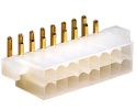
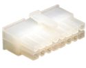
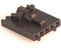
This connector is used to connect the BMS to the rest of the system.
Wiring info:
NOTE PIN NUMBERS AND TAB ORIENTATION!
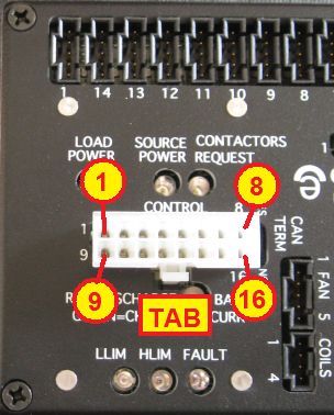
Control connector plugged into controller.
| #
| Name
| Type
| Function
| Notes
|
| 1
| GND
| Gnd
| Signal ground
| Use a separate wire from power ground, to avoid errors in analog readings.
|
| 2
| V+
| Pwr out
| Full voltage utility supply
|
Voltage present when BMS powered through either V+ line.
May be used to power equipment such as loggers, remote controllers.
|
| 3
| V+L
| Pwr in
| Power in from load
|
The BMS is powered by voltage at either terminal (uses isolating diodes).
V+L must be powered whenever the load is on, and only then.
V+S must be powered whenever the source is on, and only then.
For example, in a BEV or PHEV application, V+L is powered by Ignition, V+S is powered whenever the vehicle is plugged into AC power.
In a HEV application, V+S is powered by the ignition.
In a UPS application, V+S is powered whenever there's AC power, and V+L is powered all the time.
If only one power source is possible, use V+S.
Which input powers the BMS selects which current sensor is used. If both are powered simultaneously, the current reading may double.
|
| 4
| V+S
| Pwr in
| Power in from source
|
| 5
| Cont. Req,
| Dig in
| Contactor request
|
Requests that contactors be on.
For vehicle applications, connected to the Ignition line (off when ignition goes off).
|
| 6
| SRC
| Lin in
| Source current
|
Analog input to measure current from the source / charger
|
| 7
| 5V
| Pwr out
| 5 V utility supply
|
To power low power devices
|
| 8
| CANL
| Bus
| CAN Bus low
|
|
| 9
| PGND
| Gnd
| Power common
| Return for high current loads (contactor coils, fan, HLIM, LLIM and Fault outputs). Use a separate wire from the signal ground
|
| 10
| LLIM
| O.D. out
| Low Limit
|
Open collector, polarity selectable in software.
Activated when the most charged cell's voltage is too high (HLIM) or when the most discharged cell's voltage is too low (LLIM).
|
| 11
| HLIM
| O.D. out
| High Limit
|
| 12
| FLT
| O.D. out
| Fault
|
Open collector, polarity selectable in software. Activated in case of alarm.
|
| 13
| SOC
| Lin out
| State Of Charge analog out
|
Analog voltage: 5 V = 100 % full, down to 0 V = empty
|
| 14
| DCL
| Lin out
| Discharge Current Limit
|
Analog voltage: 5 V = no limit, down to 0 V = no current allowed.
|
| 15
| CCL
| Lin out
| Charge Current Limit
|
| 16
| CANH
| Bus
| CAN Bus high
|
|
BOTH GROUND PINS MUST BE WIRED TO THE SUPPLY!
This controller has 2 separate grounds.
- Signal ground: low current, reference for digital and analog signals
- Power ground: carries the high current for power devices: fan driver and contactor coil drivers
Both of these grounds must be connected to the negative of the low voltage supply (the 12 V nominal power supply, DC-DC converter or battery that powers the BMS), each through a separate wire.
These grounds are connected to each other on the BMS controller by a small resistor.
Grounding of the BMS.
Additionally, the metal case of enclosed controllers, which is isolated from the signal and power grounds, must be connected directly to earth or chassis.
- This is for safety reasons
- This is also required to perform the chassis isolation test (through the HV Front End)
The negative of the low voltage supply (which is connected to the signal and power grounds) may or may not be connected to the earth or chassis, as required by the application.
In general, for safety reasons, the negative of the high voltage battery (the Li-Ion pack that is managed by this BMS) should not be connected to these grounds.
Yet, if safety is not an issue, as far as the Elithion BMS is concerned, it is OK to do so.
BOTH GROUND PINS MUST BE WIRED TO THE SUPPLY!
This controller has 2 separate power inputs
- Source: on when the power source is on, such as a battery charger
- Load: on when the battery load is on, such as a motor driver
The BMS is on when there's voltage on either of these inputs.
See the specifications for the allowable voltage range and the supply currents.
Power to and from the BMS.
The BMS provides 2 power outputs for external devices:
- V+: powered whenever either power input is powered, at the highest voltage of the two
- 5V: powered at the same time, but sourcing 5 V
See the specifications for the maximum current available from these outputs.
There are 3 Open Drain Outputs on the control connector
- FLT (Fault)
- HLIM (High limit): battery unable to accept charge
- LLIM (Low limit): battery unable to accept discharge
Open drain outputs.
Additionally, there are 4 more Open Drain Outputs on other connectors
- Coils (3 each)
- FAN (1 each)
Each of these outputs is either open (clamped to V+) or connected to the power ground, depending on the state they are reporting.
- With a pull-up resistor to the 5 V supply, they can be used as TTL or CMOS logic outputs
- They can drive medium power DC loads directly, such as relays
- See the specifications for the maximum sinking current and maximum open circuit voltage for these outputs.
Note that the polarity (active open or active grounded) is programmable. See the programming instructions.
There are 3 linear (analog) outputs on the control connector
- SOC (State Of Charge)
- CCL (Charge Current Limit)
- DCL (Discharge Current Limit)

Signal outputs.
- These outputs produce a voltage in the range from 0 V to 5 V, according to the state of the condition they report
- They can drive light loads, such as the inputs of Analog to Digital converters
- They can drive resistors of no less than 5 kOhm, such as throttle pots
- See the specifications for their output resistance, and maximum voltage for these outputs.
There is one digital output on the FAN connector
- PWM (Pulse Width Modulation)
- This is a CMOS output (0 or 5 V), with a high frequency square wave of variable duty cycle, from 0% (always at 0 V: no fan) to 100 % (always at 5 V: full fan speed)
- It can drive a light load, such as the inputs of a power buffer
- It cannot drive a fan directly
There are 2 signal inputs on the control connector
- Source Current: a linear (analog) input
- Contactor request: a digital input
Signal inputs.
- The Source Current input can be driven by a charger that puts out a linear voltage proportional to the charging current
- This input responds to voltages in the range from 0 V to 5 V, but it is protected against voltages outside this range
- The Contactor Request input can be driven by the 12 V ignition line in a vehicle
- To use the contactors to disable discharge when so ordered by the BMS function
- Connect the LLIM output to the Contactor request input:
- Connect a pull up resistor (such as 1 kΩ) between LLIM and the + 12 V supply
- Configure the BMS to close the LLIM output to disable discharge
If the application includes a CAN bus, the can bus lines can be connected to it.
CAN bus connections.
- The CAN bus is referenced to the supply ground (it is not floating)
- The programming shunt next to the connector is placed on a 3-pin connector:
- In one position, it adds a 120 Ohm termination to the CAN bus
- In the other position, it doesn't add a termination
Use this port with a computer running a Terminal Emulation application, to program the BMS controller.
| On PCB
| Mate
|
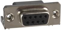
DE-9 D-Sub female
|
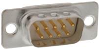
DE-9 D-Sub male plug
|
| #
| Name
| Type
| Function
| Notes
|
| 2
| TXD
| Out
| RS232 serial data
|
Implements HOST (may be connected directly to a PC, needs Null Modem for a Mac)
|
| 3
| RXD
| In
| RS232 serial data
|
| 5
| GND
| Gnd
| Control common
|
The controller can directly drive optional contactors: 2 contactors in series with each line of the battery, plus a precharge relay in series with a precharge resistor.
| On PCB
| Mate
| Pin-out
|
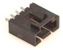
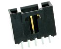
Molex C-Grid CL, 0.1" pitch
4-pin male header
|
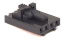
Female housing, locking: 50-57-9404 DK:WM2902-ND
Crimp socket, 22-24 AWG gold: 16-02-0103 DK:WM2512-ND
|
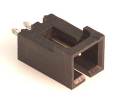
Female connector, wire entry side
|
| #
| Name
| Type
| Function
| Notes
|
| 1
| K+
| Pwr out
| Contactors' coils common (+)
|
Same as V+ on the control connector: voltage present when the BMS is powered through either V+ line.
|
| 2
| K1
| O.D. out
| Precharge relay coil (-)
|
|
| 3
| K2
| O.D. out
| Positive contactor coil (-)
|
| 4
| K3
| O.D. out
| Negative contactor coil (-)
|
Use this circuit if driving contactors from the Lithiumate Pro Master.
Contactor circuit.
The controller can control an optional fan when the cell temperature exceeds a threshold.
The controller can drive directly a low power DC fan, or a relay to control high power blowers.
To drive variable speed fans, additional electronics (not included) must be used to convert the PWM output from the controller to a variable DC voltage.
Program the BMS controller to tell it when to start driving the fan, and when to drive it at full speed.
| On PCB
| Mate
| Pin-out
|
Molex C-Grid CL, 0.1" pitch
5-pin male header
|
Female housing, locking: 50-57-9405 DK:WM2903-ND
Crimp socket, 22-24 AWG gold: 16-02-0103 DK:WM2512-ND
|
Female connector, wire entry side
|
| #
| Name
| Type
| Function
| Notes
|
| 1
| GND
| Gnd
| Control common
|
|
| 2
| PGND
| Gnd
| Power return
|
|
| 3
| FAN
| O.D. out
| Low power fan drive / drive for fan relay
|
Grounded when cooling is required
|
| 4
| FAN PWM
| Dig out
| Variable Duty Cycle Pulse Width Modulation
|
0% DC for no cooling, up to 100% DC for full cooling
|
| 5
| K+
| Pwr out
| Fan power
|
Voltage present when BMS powered through either V+ line.
|
Optional, external, cable mounted, current sensor to monitor battery current to and from the load.
Required if a current sensor is not included on the HV Front End, or there is no HV Front End, or if there is no message on the CAN bus reporting the load current.
Compatible with most 4-wire, dual 15 V supply, current sensors.
Program the BMS controller to match the current sensor's offset and gain.
| On PCB
| Mate
| Pin-out
|
Molex C-Grid CL, 0.1" pitch
4-pin male header
|
Female housing, locking: 50-57-9404 DK:WM2902-ND
Crimp socket, 22-24 AWG gold: 16-02-0103 DK:WM2512-ND
|
Female connector, wire entry side
|
| #
| Name
| Type
| Function
| Notes
|
| 1
| +15V
| -
| Positive supply
|
|
| 2
| -15V
| -
| Negative supply
|
| 3
| SIG
| Lin in
| Current sensor signal
|
| 4
| GND
| Gnd
| Signal common
|
The battery pack should be divided into 2 or more banks, up to 16 banks.
Each bank has two or more cell boards mounted on the cells.
The boards in each bank are connected to one of these connectors on the controller.
Each of these connectors sends data to the cell boards ("TX") and receives back data ("RX").
| On PCB
| Mate
| Pin-out
|
Molex C-Grid CL, 0.1" pitch
5-pin male header
|
Female housing, locking: 50-57-9405 DK:WM2903-ND
Crimp socket, 22-24 AWG gold: 16-02-0103 DK:WM2512-ND
|
Female connector, wire entry side
|
| #
| Name
| Type
| Function
| Wire color
| Notes
|
| 1
| TX
| Out
| Transmit out
| Red
| To most positive cell in the bank
|
| 2
| GND
| Gnd
| TX return
| Black
|
| 3
| Shield
| Common for both TX and RX
| -
| Do not terminate at other end
|
| 4
| Gnd
| RX return
| Green
| To most negative cell in the bank
|
| 5
| RX
| In
| Receive in
| White
|
If you don't know what an interlock* is, then it's very unlikely that you need to bother with this function: don't do anything with it, and everything will work fine.
To use this input:
- Connect the switch to the Interlock input
- In BMS controllers rev A through D, the switch must be left floating
- In BMS controllers rev E and up, the interlock input lines can be connected to any voltage between 0 and V+, either directly or through resistors, as long as the + input is more positive than the - input
- If using an N.C. switch, program program its polarity as N.C.
- If the switch is activated, the BMS will report a Fault
- Set up the system to respond appropriately to a Fault (such as turning off the contactors); otherwise, nothing will happen when the interlock switch is activated
| On PCB
| Mate
| Pin-out
|
Molex C-Grid CL, 0.1" pitch
2-pin male header
|
Female housing, locking: 50-57-9402 DK:WM2900-ND
Crimp socket, 22-24 AWG gold: 16-02-0103 DK:WM2512-ND
|

Female connector, wire entry side
|
| #
| Name
| Type
| Function
|
| 1
| -
| In
| Interlock negative input
|
| 2
| +
| In
| Interlock positive input
|
*) An interlock is a switch (normally open or normally closed) that is activated if there is a problem: for example, an inertia switch, a panic button, or a tamper switch, or a wire loop along a high voltage bus..