|
|
index  install install_comm_harness install install_comm_harness
Install - Cell board communication harness
Making a communication harness to connect a cell board to the BMS controller

 Li-Ion batteries are dangerous!
- Wear safety glasses.
- Do not allow conductive objects (tools, solder...) to come into contact with cells or Cell Board
- Do not touch more than one battery connection at the same time
Unfortunately, we do not have the resources to teach all of our clients proper assembly procedures, which are essential for a succesful project.
What we can do is pass along this info to you:
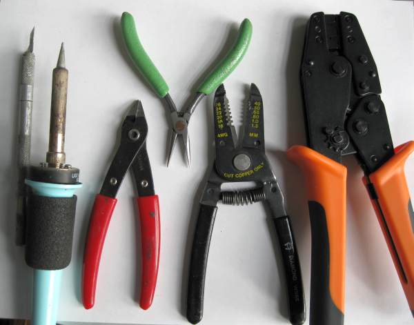
Required tools
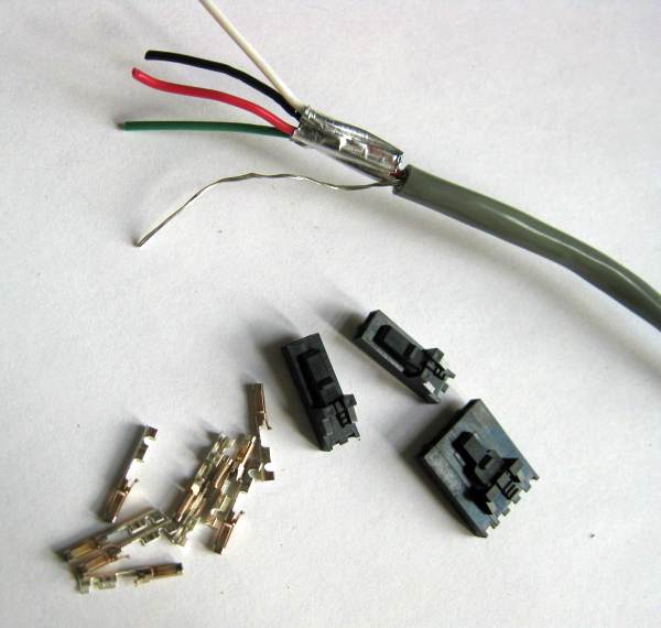
Required parts
- Route the cable from the BMS controller to the bank, to its farthest end
- Cut the cable
- Unclad the cable 1" (25 mm)
- Remove the foil, keep the bleed wire (the uninsulated wire)
- Strip each of the 4 insulated wires 1/8" (6 mm)
- Crimp a female socket to each of the 5 wires, using the 24 AWG slot in the tool
- Slip the sockets in a 5-pin housing
- TX - red (pin 1 is marked by a triangle embossed in the plastic)
- GND - black
- GND - bleed wire
- GND - green
- RX - white
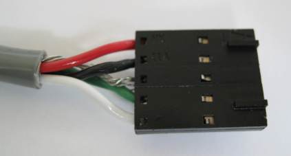
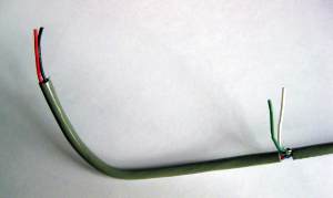
Cell Board harness, BMS controller end
- Place the end of the cable by the farthest point of the bank
- Route the cable towards the other end of the bank
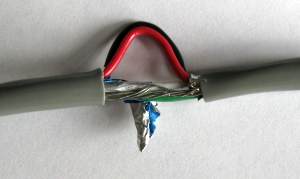
- At that location, use an Exacto knife to cut the cladding, careful not to cut into the wires
- Slip the cladding out about 2" (50 mm)
- Open the foil to reach the wires
- Locate the 2 wires for that end of the bank:
- If at the positive end of the bank, pull out the red and black wires
- If at the negative end of the bank, pull out the green and white wires
- Pull out the 2 wires just a few inches
- Cut the 2 wires about 1" (25 mm) from the cladding going towards the BMS controller
- Slip the cladding back in, to meet the other cladding
- Unclad the cladding at the other end 1" (25 mm)
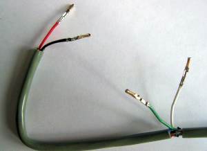
Cell Board harness preparation, Cell Board end, if the positive end of the bank is farthest from the BMS controller
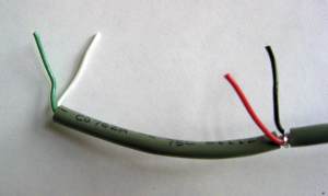
Cell Board harness preparation, Cell Board end, if the negative end of the bank is farthest from the BMS controller
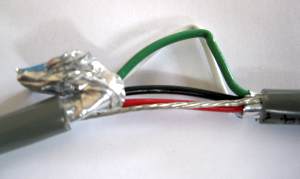
- Remove the foil at the end of the cable and cut off the bleed wire (the uninsulated wire)
- Strip each of the 4 insulated wires 1/4" (12 mm)
- Tin the wire ends
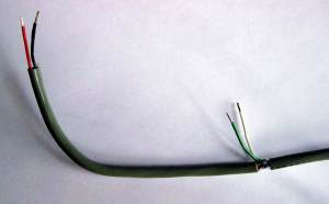
Cell Board harness, Cell Board end, to be soldered to Cell Board
- Remove the foil at the end of the cable and cut off the bleed wire (the uninsulated wire)
- Strip each of the 4 insulated wires 1/8" (6 mm)
- Crimp a female socket to each of the 5 wires, using the 24 AWG slot in the tool
- Slip the sockets in a 2 2-pin housings
- Positive end of battery:
- GND - black (pin 1 is marked by a triangle embossed in the plastic)
- TX - red
- Negative end of battery:
- GND - green (pin 1 is marked by a triangle embossed in the plastic)
- TX - white
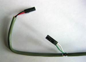
Cell Board harness, Cell Board end, with connectors

|
|