This application note describes how to manage a battery array with multiple sections in series.
Typical applications:
- High voltage batteries with more than 256 cells in series
- Large batteries distributed in multiple locations
The entire string is divided into sections, each with at most 256 cells in series, monitored by its own BMS master ("Section Master").
An "Array Master" manages the entire battery.
The external system monitors and controls the entire battery through the Array Master (through the CAN bus and / or through dedicated lines)
Maximum battery voltage:
The total battery voltage is limited to 1.5 kV by the isolation of the end cell boards.
To operate at higher voltages, each BMS master must be isolated, using an isolated DC-DC converter and CAN bus isolator,
each rated for the full battery voltage.
Wiring
Required components:
- A cell board for each cell in series
- A Section master for each section of the battery
- An Array Master (a BMS master programmed with that special function)
- A current sensor
- As needed: Fuses, safety disconnects, contactors, fans...
Note that HVFEs cannot be used, because they are not rated for such high voltages.

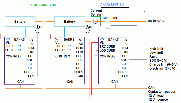
Block diagram of a BMS for an array of batteries in series
- Connect each Section Master to the cell board banks of its own battery section
- Power each Section Master through its VL input, from the V+ output of the Array master
- Connect any fans to the each Section Master
- Connect the current sensor to the Array Master
- Connect any contactors to the Array Master
- Connect the CAN bus to all devices, and to the external system (if applicable)
- If the external system uses any dedicated line (such as HLIM, LLIM, contactor request), connect them to the Array Master
- If the application as two separate modes of operation for charging and discharging (e.g.: an Electric Vehicle),
power the Array Master through VS when in the charging mode (e.g.: AC power present),
and VL when in the operating mode (e.g.: ignition);
otherwise, power he Array Master through the VS input only
Communication
The external system may use the CAN bus and the RS232 connector of the Array Master.
For configuration and monitoring of each Master (Section or Array), use its RS232 connector.
For Section Masters, use the standard GUI. For the Array Master, use the special Array GUI for Windows.
During operation, while is is possible to monitor each Section Master through its RS232 connector
(i.e.: through the standard GUI), that is not necessary, as it is easier to monitor the entire battery through the special Array GUI.
Note that the system uses a single. common CAN bus for both external and internal communications.
Therefore, the external system sees communications internal to the BMS, and is able to monitor each Section Master.
Configuration
Configure the Section Masters:
- Configure for the number of cells
- Configure the balancing settings
- If a fan is used, set it up
- Set up the CAN bus:
- Set each Section Master for a different PID ID: 7E1h for the first one, 7E2h for the second one, etc.
- Set each Section Master for a different custom message ID: 6E1h for the first one, 6E2h for the second one, etc.
- Set the custom message to 0.01 s rate and 5 data bytes
- Set the custom message data:
- 0: 24 1 1 0 (Minimum cell voltage)
- 1: 46 1 1 0 (Maximum cell voltage)
- 2: 88 1 1 0 (Minimum temperature)
- 3: 104 1 1 0 (Maximum temperature)
- 4: 136 1 1 0 (Flags 1)
- Turn off all other CAN transmitted messages: Standard messages, Data dump. Elithion messages, Messages to devices
- All other settings have no effect, so you may leave them at their defaults
Configure the Array Master as you would any standard BMS master, except:
- Configure for the number of batteries (the number of Section Masters)
- Configure for 0 cells and banks


