|
|
index  install install_local_hvfe install install_local_hvfe
Install - Local HVFE
Installation instructions for the 2HV0xxxB Local HV Front End.

The HFVE lines are isolated, so you way wire it as appropriate for your application.
One possible wiring approach is shown here:
Suggested wiring schematic.
- If the battery voltage is sensed (for Battery Voltage test or for isolation test), connect the B+ and B- terminals to the battery terminals
- The current may be sensed either before or after the contactors (before the contactors if you want to test for battery voltage before turning on the contactors)
- Before the contactors if you want to test for battery voltage presence before turning on the contactors
- Before the contactors if you want to test for battery isolation before turning on the contactors
- Respect polarity (no damage occurs if you don't)
- If a current sensor is used, route the battery current through the current sense contacts.
- The current may be sensed either before or after the contactors
- The current may be sensed either on the positive or the negative battery terminal
- Respect polarity (if you don't, you can reverse the direction through programming)
- If the voltage across a precharge resistor is sensed (for precharge tests), connect its ends to the P+ and P- terminals
- The precharge resistor may be placed on either side of the precharge relay
- The precharge circuit may be placed on the positive or the negative battery terminal
- Respect polarity (no damage occurs if you don't)
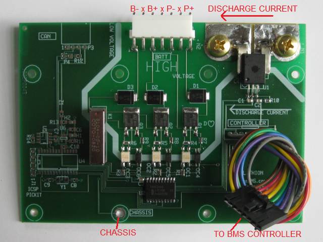
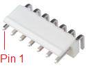
Connectors on board level, local High Voltage Front End, PCB rev B.
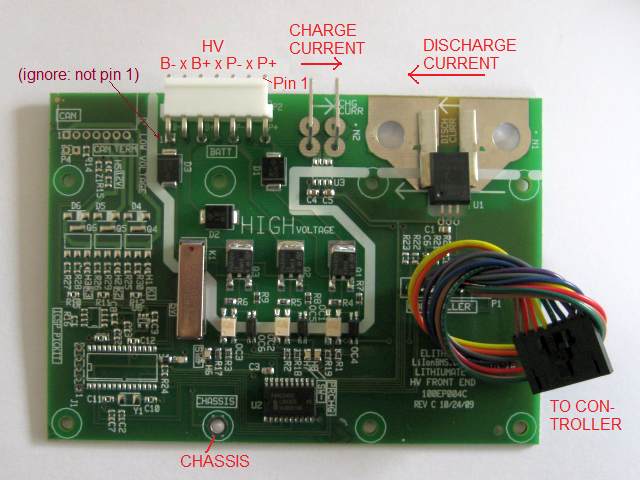
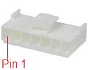
Connectors on board level, local High Voltage Front End, PCB rev C.
Note that at most only one current sensor is available: 5 or 20 A (center) or 50 to 200 A (right).
This connector is connected to the high voltage (connected to the battery).
This connector has 3 functions:
- Detects the presence of voltage across the precharge resistor (if you have one)
- Wire the precharge resistor if you want to stop precharge when the voltage across the resistor drops to a low value, or you want to test the proper operation of the precharge circuit and contactors
- Use pins 1 and 3
- Detects the presence of voltage across the battery terminals
- Wire the battery terminals if, before turning on the contactors, you want to make sure that battery voltage is present
- Use pins 5 and 7
- Detects any current path between the battery and the chassis
- Wire the battery terminals if, before turning on the contactors, you want to make sure that the battery is isolated from the chassis
- Use pins 5 and 7 and make sure the PCB (2HR0xxxB) or case (2HR0xxxE) is grounded to the chassis
| #
| Name
| Type
| Function
| Notes
|
| 1
| P+
| In
| Precharge positive end
If the resistor is in series with the positive lead, this is the resistor lead towards the battery
|
To sense the precharge current (the voltage drop across the precharge resistor).
|
| 3
| P-
| In
| Precharge resistor negative end
If the resistor is in series with the positive lead, this is the resistor lead towards the load
|
| 5
| B+
| In
| Battery positive terminal
|
To sense leaks to chassis due to loss of isolation, and presence of battery voltage.
|
| 7
| B-
| In
| Battery negative terminal
|
The pin numbers are on the housing (on rev C PCBs the '1' on the silk screen is on the wrong side)
When installed, pin # 1 is closest to the center of the board.
Odd-numbered pins are unused to improve high voltage rating.
The resistor pins are isolated from the battery pins; therefore, the precharge resistor may be placed on either battery polarity, and on either side of a contactor.
Inputs are protected against polarity reversal.
- Use wire rated for the battery voltage, such as 300 V, 600 V or 100 V; if unavailable, run the wire through tubing for additional insulation
- Use wire between 22 and 18 AWG (between 0.5 and 1 mm2)
- Strip the wires 0.1"e / 2 mm
- Crimp the wires into the VHR female terminals
- Slip the terminals into the VHR housing, until they snap in place
In order for the chassis insulation test to work, the case (or PCB ground plane) of the HV Front End must be connected to the chassis.
The HVFE can be used to measure battery current (5, 20, 50, 100 or 200 A).
(Not applicable to the 2HV0000B, which does not include an on-board current sensor.)
The connection for low current (5 or 20 A, usually for the source current) is different from the connection for high current (50 A to 200 A, ususally for load current).
For low current: (2HV0005B and 2HV0020B):
| On PCB
| Mate
|
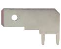
Right angle 1/4" male quick connect tab terminal
|
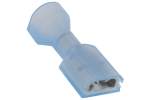
1/4" female quick connect tab terminal
Red: 18-22 AWG; blue: 14-16 AWG
|
- Use an appropriate wire size for the average current (peak current can be higher)
- Use wire rated for the battery voltage, such as 300 V, 600 V or 100 V; if unavailable, run the wire through tubing for additional insulation
- For 5 A use 22 AWG / 0.5 mm2 wire or greater
- For 10 A use 20 AWG / 0.5 mm2 wire or greater
- For 20 A use 16 AWG / 1.5 mm2 wire or greater
- Use female quick-connect tab terminals
- Size: 1/4" x 0.032", fully insulated straight
- For 16 AWG wire use 14-16 AWG terminals, blue insulation
- 3M: 94820, FDI14-250C, MNU14-250DFIK
- Tyco 3-350820-2, 3-520408-2, 3-520117-2, 3-520141-2
- Molex 19003-0044, 19003-0040, 19003-0040, 19002-0024
- For smaller wire use 18-22 AWG terminals, red insulation
- 3M: 94803, FDI18-250C, MNU18-250DFIK
- Tyco 2-520184-4, 2-520184-2, 2-520264-2, 2-520407-2
- Molex 19002-0001, 19005-0001, 19003-0001
- Strip the wires as appropriate for the crimp barrel of the terminal
- Crimp the wires into the terminals
- Slip the terminals into the tabs in the HVFE, so that the charging current flows from the right terminal to the left terminal (from the terminal closest to the white connector, to the terminal closest to the high current connectors)
- If placing it on the positive wire: connect the right terminal to the red wire going to the charger '+' output, and the left terminal to the red wire going to the battery '+' terminal
- If placing it on the negative wire: connect the left terminal to the black wire going to the charger '-' output, and the right terminal to the black wire going to the battery '-' terminal
For High current: (2HV0050B, 2HV0100B and 2HV0200B):
| On PCB
| Mate
|
|
M5 threaded insert
|
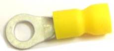
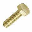
Size 10 or M5 ring terminal; M5 bolt
|
- Use an appropriate wire size for the average current (peak current can be higher)
- Use wire rated for the battery voltage, such as 300 V, 600 V or 100 V; if unavailable, run the wire through tubing for additional insulation
- For 25 A use 14 AWG / 2.5 mm2 wire or greater
- For 50 A use 10 AWG / 6 mm2 wire or greater
- For 100 A use 6 AWG / 16 mm2 wire or greater
- For 200 A use 1/0 AWG / 50 mm2 wire or greater
- Use straight ring terminals for the M5 bolts used on the HVFE
- Stud size: 5 mm, 10 Gauge (1/4" will work but will be sloppy)
- Max OD: 0.5" / 12.7 mm
- Crimp size: appropriate for wire used; the Outer Diameter of terminals for large wire sizes is more than 0.5", so you may need to file them down
- If the terminal is not insulated, use heat shrink to insulate
- Some suggested parts:
- 14 AWG: Tyco 36160, 34161, 32960, 320574, 51864-2, 31903, 324533, 696423-6, 53418-1, 51864-9, 320630; 3M MVU14-10RK, 94728, 94729; Panduit PV14-10R-M, PV14-10R-C, Molex 19070-0102, 19073-0087, 19070-0090
- 12 AWG: 3M 94741, MVU10-10RK; Tyco 696424-6, 324918, 2-36161-3, 32883, 50845-2, 35364, 36161, 34854, 35109; Molex 19073-0170
- 10 AWG: 3M 94741, MVU10-10RK; Tyco 696424-6, 324918, 2-36161-4, 32883, 50845-2, 35364, 36161, 34854, 35109; Molex 19073-0170
- 8 AWG: Tyco 52263-1, 52263, 324043
- 6 AWG: Tyco 52042-4, 53119-1, 324046, 52265
- 4 AWG: (not insulated) Tyco 33114, Molex 19193-0273
- 2 AWG: (not insulated, 0.62" OD) Tyco 330301
- 1/0 AWG: (not insulated, 0.87" OD) Tyco 160000
- Strip the wires as appropriate for the crimp barrel of the terminal
- Crimp the wires into the terminals
- 2HR0xxxE: open the case of the HVFE (4 screws)
- Remove the two M5 bolts for teh high current sensor
- Place the M5 bolts through the washer and through the terminals, then screw into the PCB assembly, so that the discharging current flows from the left terminal to the right terminal (from the terminal closest to the end of the board, to the terminal closest to the white connector)
- If placing it on the positive wire: connect the right terminal to the red wire going to the load '+' input, and the left terminal to the red wire going to the battery '+' terminal
- If placing it on the negative wire: connect the left terminal to the black wire going to the load '-' input, and the right terminal to the black wire going to the battery '-' terminal
- Tighten the M5 bolts 50 inch-pounds / 6 Nm
- 2HR0xxxE: close the case of the HVFE (4 screws)
Unfortunately, we do not have the resources to teach all of our clients proper assembly procedures, which are essential for a succesful project.
What we can do is pass along this info to you:
This connector is used to connect the HV Front end to the BMS controller.
The 8-pin connector at the end of the 8-wire harness is plugged into to the 8-pin connector on the BMS controller.
Mount the PCB assembly with 8 screws or bolts, with a maximum size of 4-40 / M3.
The HVFE can be used to measure battery insulation before turning in the contactors. In that case, the hole marked "CHASSIS" must be grounded reliably.

|
|