The mounting method is not specified, as mechanical and thermal considerations depend on the particular application and on the format of the cells used.
Mounting holes are provided, and one of the surfaces is completely flat, allowing surface mounting.
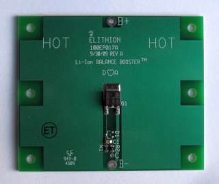
When deciding on how to mount a Balance Booster, take into consideration that its temperature when on is about 100 °C hotter than ambient.
Therefore, it is not advisable to mount it directly on a cell.
- Small Cylindrical: the 2.5" dimension of the board matches the length of small cylindrical cells;
this suggests mounting it physically in parallel with the cells, though at some distance away.
- Prismatic: With cell in the normal orientation (vertical), the board may be mounted also vertically, for example mounted on strips of non-conductive material that are inserted in the grooves between cells.
In any case, the board can be mounted some distance from the cell board, as its wires may be long without a problem.
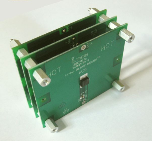
Multiple Balance Boosters may be connected and mounded in parallel, to increase the balance current.
- The 'B+' of all balance boosters are connected to the cell's '+' terminal
- The 'B-' of all balance boosters are connected to the cell's '-' terminal
- The 'C' of all balance boosters are connected together, and then to the cell board's 'C' terminal
Suggested wires:
- 'B+': 18 AWG, red
- 'B-': 18 AWG, black
- 'C': 24 AWG, white
Instructions:
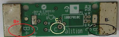
- Use a red wire to connect the 'B+' terminal of the Balance Booster to the 'B+' pad of the cell board
- Use a black wire to connect the 'B-' terminal of the Balance Booster to the 'B-' pad of the cell board
- Use a white wire to connect the 'C' terminal of the top Balance Booster to the 'C' pad of the cell board
Instructions:
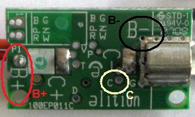
- Use a red wire to connect the 'B+' terminal of the Balance Booster to the 'B+' pad of the cell board
- Use a black wire to connect the 'B-' terminal of the Balance Booster to the 'B-' pad of the cell board
- Use a white wire to connect the 'C' terminal of the top Balance Booster to the 'C' pad of the cell board
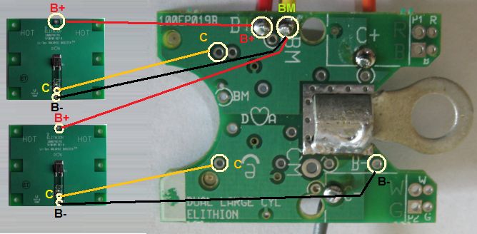
Large cyclindrical cell boards have 2 circuits on one PCB assembly, and therefore take 2 Balance Boosters.
Instructions:
- Use a red wire to connect the 'B+' terminal of the top Balance Booster to the 'B+' pad of the cell board
- Use a black wire to connect the 'B-' terminal of the top Balance Booster to the 'BM' pad of the cell board
- Use a white wire to connect the 'C' terminal of the top Balance Booster to the top 'C' pad of the cell board
- Use a red wire to connect the 'B+' terminal of the bottom Balance Booster to the 'BM' pad of the cell board
- Use a black wire to connect the 'B-' terminal of the bottom Balance Booster to the 'B-' pad of the cell board
- Use a white wire to connect the 'C' terminal of the bottom Balance Booster to the bottom 'C' pad of the cell board