
The BMS is an integral part of the battery pack, as well as a major component in the complete system.
System block diagram.
The complete system consists of:
- A battery
- A Source, such as a charger, (if applicable)
- A Load, such as a motor controller
- A BMS
The Battery is connected to:
- The Source, which charges (and may discharge) the battery
- The Load, which discharges (and may charge) the battery
The BMS receives power from:
- The Source (such as a charger, whenever plugged in to an outlet)
- The Load (such as a motor driver, whenever a vehicle's ignition is on)
The BMS is connected to:
- The cells in the battery pack, to measure their conditions and to balance them
- The Source, to tell it when to stop charging (or discharging) the battery
- The Load, to tell it when to stop discharging (or charging) the battery
Whenever the BMS is powered (by either the source or the load), it performs the following functions:
Most parameters are adjustable.
BMS functions.
The BMS may be powered by either of two power sources, and is able to detect which one
- Source (e.g.: charger)
- Load (e.g.: motor controller)
More detailed info.
Detects inputs
- Where its power is coming from (source and/or load)
- If there's a request to turn on the contactors
- If the interlock input is open or closed
As it turns on the contactors, it may perform some tests (depending on whether an HVFE is present and on the external circuit)
- Pack presence / isolation
- Contactor, relay and precharge resistor conditions
- Normal precharge current wave-shape
More detailed info.
Measures battery pack parameters
- The voltage of each cell
- The temperature of each cell board
- The battery current (from/to the source and/or the load)
More detailed info.
The BMS computes
- An estimate of the Depth Of Discharge (DOD)
- An estimate of the State Of Charge (SOC)
- An estimate of the cells' internal resistance, and of the pack's total resistance
- An estimate of the pack's actual capacity
- An estimate of the pack's State Of Health (SOH)
- A Charge Current Limit (CCL) and Discharge Current Limit (DCL)
More detailed info.
The BMS manages the battery directly by
- Balancing the charge in the cells
- Driving a cooling fan or blower (if present)
The BMS manages the battery indirectly, by
- Requesting that the Source and the Load reduce or even stop the battery current
More detailed info.
The BMS drives logic outputs
- HLIM = High Limit: active is the battery cannot accept charge
- LLIM = Low Limit: active is the battery cannot deliver charge
- FLT = Fault: active is the BMS has detected a fault
- K1, K2 and K3 = Contactor (relay) drive
The BMS drives analog outputs
- CCL = Charge Current Limit: normally 5 V, down to 0 V as the battery cannot accept charge
- DCL = Discharge Current Limit: normally 5 V, down to 0 V as the battery cannot deliver charge
- SOC = State of Charge: from 5 V, down to 0 V as the battery is discharged
More detailed info.
CAN bus
- Reads data from the CAN bus
- Any requests to turn on the contactors
- Battery current (if available)
- State of the High Voltage Front End (if used)
- Places messages on the CAN bus
- Standard messages
- Messages to the SOC display (if used)
- Messages to the High Voltage Front End (if used)
- Messages for particular external devices, such as a charger
- Custom messages, (as configured by the user)
RS232 serial port
- Command line user interface
- May output a select set of the readings, once a second
More detailed info.
Level faults
- After a status fault condition (such as over-current) is present for a certain length of time, it starts reporting a fault
- As soon as all status fault conditions are cleared, it stops reporting a fault
Transitory faults
- As soon as a transitory condition occurs (such as a failed contactor test), it starts reporting a fault
- This fault conditions is cleared by cycling the power off and on
More detailed info.
During installation or service, the user may connect a terminal to the RS232 serial port to:
More detailed info.
The BMS controller may be powered by two sources, and is able to detects which one has power.
- Source, through the VS pin of the control connector
- Load, through the VL pin of the control connector
For example, in an EV, the VS line is powered from the a supply that is on when the vehicle is plugged in;
while the VL line is powered from the vehicle's sustain ignition, which is on when the vehicle is on, and a bit afterwards.
See this tip on vehicle ignition for suggestions on how to wire the power in an EV.
Whenever either the Source or the Load is on, the BMS controller outputs 4 voltages for external use:
- V+, on the control connector
- Voltage is close to the maximum of either VS or VL
- This is typically used for contactors, low power fans, accessories such as remote control or data loggers.
- 5V, on the control connector
- Provides of 5 Volts, at low current
- Available for very small loads, such as 5 V current sensors
- +15V and -15V, on the Ext Cur Snsr connector
- Provides a very low current source of + and - 15 Volts
- Available for very small loads, such as +/- 15 V current sensors
The BMS controller has 2 ground connections:
- Signal ground
- Power ground
Both grounds must be connected to the negative of the low voltage supply!
The BMS controller sees if the interlock input is open or closed, from the Interlock connector.
It also sees if the there is a request for the contactors to be on, from the ContReq pin of the control connector.
If the optional High Voltage Front End is used, it can be used to run certain tests before turning on the contactors:
- Pack presence / isolation
- Contactor, relay and precharge resistor conditions
- Normal precharge current wave-shape
In addition, the BMS detects which power source is used (see above), and, from the CAN bss, it may read the battery current (see below) and, any requests to turn on or off the contactors (see below).
The BMS measures the cell voltages, the cell board temperatures and the battery current, and calculates minimums, maximums and averages.
- The BMS measures the voltage of each set of cells in parallel.
- It determines the voltage of the most charged and of the most discharged sets, and calculates the average cell voltage
- It calculates a time-average of the minimum cell voltage and of the maximum cell voltage (the BMS bases its behavior on these values, to avoid premature decision based on instantaneous values)
- It adds all the voltages in a series string to get the pack voltage
- The BMS measures the temperature of each cell board (not the temperature of the cells themselves), which is an indirect measurement of the cell it is connected to
- It determines the temperature of the hottest and of the coldest cell boards, and calculates the average temperature
- It calculates a time-average of the hottest and coldest temperature (the BMS bases its behavior on these values, to avoid premature decision based on instantaneous values)
Note that the temperature seen will be higher during balancing, due to the heat from the balancing resistor.
The BMS controller reads the current in one of 4, selectable ways:
- Through the CAN bus, or
- From a +/1 15 V current sensor connected to the Ext Curr Snsr connector, or
- From a 5 V current sensor connected to the SrcCur pin on the control connector, or
- From a current sensor mounted on the optional High Voltage Front End
It is also possible not to select any source at all.
The source of battery current information is independently selectable depending on whether the Source or the Load is on at the time:
- If the BMS controller is powered through the VS pin, it reads the pack current from whichever input is programmed for Source Current
- If the BMS controller is powered through the VL pin, it reads the pack current from whichever input is programmed for Load Current
- If the BMS controller is powered through both pins, it determines the pack current as the sum of the Source Current and the Load Current
- NOTE: In that case, you must make sure that the same current is not reported twice, once as Source Current, and once and Load Current (else, the BMS will think that the current is twice as high).
The BMS controller can read the current from the CAN bus, from a message and byte with a certain scale factor and offset, all of which are programmable.
It is also possible to ignore the reading from the CAN bus, by programming a non-existent CAN ID, or setting the units to 0.
If not from the CAN bus, the BMS can measure the current from one of the 3 analog inputs described above, with programmable input, offset, gain and direction.
For example, the default setting for the Ext Curr Snsr input is: 0 V = no battery current, 5 V = 125 A out of the battery, and -5 V = 125 A into the battery,
The BMS uses the above measurements to calculate certain parameters: DOD (and SOC), Resistance, Capacity and current limits.
It uses those values to do its job of managing the battery, and it reports them through the CAN Bus.
Depth Of Discharge (DOD) is a measure of the electricity that is extracted from a battery.
It starts at 0 when the battery is full, and increases as the battery is depleted.
Its units are usually AH.
There is no direct way of measuring the Depth Of Discharge of a battery.
No indirect method is of measuring it is accurate, as explained in this white paper on Li-Ion SOC estimation
This BMS controller uses a combination of two methods:
- It normally uses "Coulomb Counting", clamped so that it won't go negative
- It calibrates the DOD to 0 when the most charged cell is fully charged
The BMS controller calculates DOD [Ah] as:
- DOD = ∫(Ibatt * dt)
- If (Vcell-max > Vcell-chgd) DOD = 0
In general, State Of Charge (SOC) is the reverse of DOD: it starts at 0 when the battery is empty, and increases as the battery is charged.
Its units are usually in %.
It is a more standard measure of state of the battery's charge than DOD.
However, unlike DOD, it suffers as it could exceed 100 % when the battery is fully charged, and could go negative when the battery is fully discharged at a slow rate.
In this BMS, the SOC is different from the DOD because:
- DOD is calculated only from the battery current (coulomb counting)
- SOC is calculated only from the battery current in the center of its range, but with voltage translation at the 2 ends: full and empty
Please see a white paper on Li-Ion SOC estimation.
The BMS estimates the SOC based on points taken from the voltage vs. SOC curve for the cells used.
Typical voltage vs SOC curve for a LiFePO4 cell.
When configuring the BMS for those cells, you will need to look at the voltage vs. SOC curve on their spec sheet.
- Look at the curve for the lowest current discharge, such as for 1C discharge.
- Draw 3 straight lines on that curve, to approximate it:
- Along the flat portion in the middle of the curve
- From the 100 % SOC point, down to the 1st line
- From the 0 % SOC point, up to the 1st line
- Mark 4 points:
- 100 % SOC ("Full point")
- Junction of the 2 straight lines at the charged end ("Charged point")
- Junction of the 2 straight lines at the discharged end ("Discharged point")
- 0 % SOC ("Empty point")
- Get data about those 4 points:
- Voltage at the "Full point"
- Voltage at the "Charged point"
- SOC at the "Charged point"
- Voltage at the "Discharged point"
- SOC at the "Discharged point"
- Voltage at the "Empty point"
- Configure the BMS using those data
The BMS estimates the SOC using 2 different methods:
- Voltage translation, along the 2 straight lines at the 2 ends
- Current integration (Coulomb counting), in the middle section
SOC calculation: gray = voltage translation; tan area: current integration.
The BMS uses those 4 points to estimate the SOC:
- Above the "Charged point" and below the "Discharged point", the BMS uses voltage translation
- When the voltage of the most charged cell is above Vchg-pt, the BMS estimates the SOC as a straight line between the "Full" and "Charged" points
- When the voltage of the least charged cell is below Vdisch-pt, the BMS estimates the SOC as a straight line between the "Discharged" and "Empty" points
- In between the "Charged point" and the "Discharged point", the BMS uses current integration (Coulomb counting) from the Depth Of Discharge: SOC = 100 * (1 - DOD / Nominal Capacity)
The dynamic resistance of the battery is a measure of its internal DC resistance under load (as opposed to AC impedance at 1 kHz).
It is the slope of a straight line that goes between two operating points in the battery's I-V curve.
It is affected by DOD, temperature and age of the battery.
In order to measure resistance, the BMS must be able to measure the battery current, and the battery current must vary.
If the battery current is 0 (or the current sensor is not installed), or the battery current is constant, the BMS cannot measure the resistance.
The BMS calculates the resistance of each set of cells in parallel, by taking multiple snapshots of their voltage at a given current.
This works well for applications in which the current varies considerably during use.
- For "Charge Sustain" applications (such as HEVs (Hybrid cars), the points are taken at a high charge current and a high discharge current.
- For "Charge Deplete" applications (such as BEVs (Electric cars), the points are taken at a high discharge current and a low discharge current, as there may never be a point with high charge current.
- For applications that use a constant current (such as a typical UPS) there is no way of measuring cell resistance, as there is only one data point.
The BMS determines the resistance of the most charged and of the most discharged sets of cells, and calculates the average resistance.
It adds all the resistances in a series string (divided by the number of batteries in parallel, if that's the case), to get the pack resistance.
Battery capacity can only be measured in applications that fully charge and discharge the battery, such as PHEVs.
In BEVs it is never desirable to completely run out of juice, so measuring the capacity may not be possible.
In HEVs the battery never reaches either end of the DOD, so capacity measurement is not possible.
In those cases that capacity can be measured, it is the DOD at full discharge.
Because of the possibility of DOD drift, this is only done during a cycle that starts from fully charged and doesn't include any long period of other than discharge.
In those cases that capacity cannot be measured, the nominal capacity is used instead.
State Of Health (SOH) is normally 100 % and decreases as the battery is considered to be less than perfect.
It is not strictly defined, and is implemented differently by different manufacturers.
The BMS controller uses a combination of Cell Resistance (if available) and Actual Capacity (if available) to calculate SOH.
Therefore, it is not able to calculate SOH in applications that draw constant current and that do not charge and discharge the battery completely.
The BMS controller calculates a CCL (Charge Current Limit) and sends it to the devices that are able to charge the battery, to request that that limit not be exceeded.
The rest of the system must pay heed to the CCL, to prevent damaging the battery.
For example, the HLIM line could be connected to the battery charger, to shut it down.
Or, the CCL could be sent to a motor inverter to disable regenerative braking.
The BMS controller calculates the CCL based on:
- The voltage of the most charged cells
- The temperature of the coldest and hottest cells
- The pack voltage
The purpose of the first two is to protect the battery.
Therefore, normally, the CCL settings are based solely on the cell specifications, not on the system capability.
That is, if a 100 Ah cell can handle a 0.5 C charge continuous, and a 3 C peak charge, then the BMS settings should be 50 A continuous and 300 A peak.
The fact that the charger can only put out 5 A has no bearing on these settings.
And, if regen can generate 500 A, that doesn't mean that you set the peak CCL to 500 A! No! The peak CCL is based on the cell capability (300 A peak in this example), not on the system capability (500 A peak in this example).
The BMS is protecting the cells, so don't set the limits beyond the cell's specifications.
The purpose of the 3rd one is to protect the system and is optional.
By default the pack voltage limits are set at extreme values, so that it never has an effect.
You should use the pack voltage limit only if there's a component in the system that cannot handle too high a pack voltage.
The CCL is determined by cell voltage, pack voltage and temperature.
| Parameter
| 100 % = normal
| Between 0% and 100% = reduced charging
| 0% = charging is disabled
|
| Voltage of most charged cell
| < Vcell-high
between Vcell-high and Vcell-max
> Vcell-max
| Pack voltage
| < Vpack-high
between Vpack-high and Vpack-max
> Vpack-max
| Temperature of hottest cell
| < Tchg-high
between Tchg-high and Tchg-max
> Tchg-max
| Temperature of coldest cell
| > Tchg-low
between Tchg-min and Tchg-low
| < Tchg-min
| | | | | | | | | | | |
The CCL will be set by whichever one of the above 3 items is most limiting.
The CCL affects the HLIM, the CCL analog output, and the CCL value [A] on the CAN bus.
In turn, the CCL then affects the BMS's outputs:
- The HLIM line is activated whenever the CCL reaches 0%, and dis-activated when it reaches 100%
- The CCL output analog line is proportional to the CCL: 5 V at 100%, down to 0 V at 0%
- The CCL value (in Amps) that BMS put on the CAN bus is proportional to the CCL: the Maximum Charging Current (as programmed) at 100%, down to 0 A at 0 %
In a typical situation:
- While the battery can accept the full charging current, the internal value for the CCL is 100%:
- The HLIM line is inactive
- The CCL output analog line is at 5 V
- The CCL value (in Amps) that BMS put on the CAN bus is the Maximum Charging Current that was programmed into it
- If the battery's charging acceptance is reduced, the internal value for the CCL goes below 100%:
the BMS starts reducing the CCL:
- For the time being, the HLIM line remains inactive
- The CCL output analog line goes below 5 V
- The CCL value (in Amps) that BMS put on the CAN bus goes below the Maximum Charging Current that was programmed into it
- Finally, when the battery's charging acceptance is down to 0, the internal value for the CCL is 0%:
- The HLIM line goes active
- The CCL output analog line is 0 V
- The CCL value that BMS put on the CAN bus is 0 Amps
- Eventually, when the battery is again able to accept charging, the internal value for the CCL goes above 0%:
- The HLIM line remains active (giving it some hysteresis)
- The CCL output analog line goes above 0 V
- The CCL value that BMS put on the CAN bus goes above 0 Amps
- Finally, when the battery can accept full charge, the internal value for the CCL is back to 100%:
- The HLIM line goes inactive
- The CCL output analog line is back to 5 V
- The CCL value that BMS put on the CAN bus is back to the Maximum Charging Current that was programmed into it
The BMS controller calculates a DCL (Discharge Current Limit) and sends it to the devices that are able to discharge the battery, to request that that limit not be exceeded.
The rest of the system must pay heed to the DCL, to prevent damaging the battery.
For example, the LLIM line could be connected to a motor inverter to disable it.
The DCL works in an analogous way to the CCL (above).
The BMS controller calculates the CCL based on:
- The voltage of the most discharged cells
- The pack voltage
- The temperature of the coldest and hottest cells
The purpose of the first two is to protect the battery.
Therefore, normally, the DCL settings are based solely on the cell specifications, not on the system capability.
That is, if a 100 Ah cell can handle a 1 C charge continuous, and a 5 C peak discharge, then the BMS settings should be 100 A continuous and 500 A peak.
The fact that the load can draw 1000 A doesn't mean that you set the peak DCL to 1000 A! No! The peak DCL is based on the cell capability (500 A peak in this example), not on the system capability (1000 A peak in this example).
The BMS is protecting the cells, so don't set the limits beyond the cell's specifications.
The purpose of the 3rd one is to protect the system and is optional.
By default the pack voltage limits are set at extreme values, so that it never has an effect.
You should use the pack voltage limit only if the load cannot handle too low a pack voltage.
The DCL is determined by cell voltage, pack voltage and temperature.
| Parameter
| 100 % = normal
| Between 0% and 100% = reduced discharging
| 0% = discharging is disabled
|
| Voltage of least charged cell
| > Vcell-low
between Vcell-min and Vcell-low
< Vcell-min
| Pack voltage
| > Vpack-low
between Vpack-low and Vpack-min
< Vpack-min
| Temperature of hottest cell
| < Tdisch-high
between Tdisch-high and Tdisch-max
> Tdisch-max
| Temperature of coldest cell
| > Tdisch-low
between Tdisch-min and Tdisch-low
| < Tdisch-min
| | | | | | | | | | | |
The DCL will be set by whichever one of the above 3 items is most limiting.
The DCL affects the LLIM, the DCL analog output, and the DCL value [A] on the CAN bus.
In turn, the DCL then affects the BMS's outputs:
- The LLIM line is activated whenever the DCL reaches 0%, and dis-activated when it reaches 100%
- The DCL output analog line is proportional to the DCL: 5 V at 100%, down to 0 V at 0%
- The DCL value (in Amps) that BMS put on the CAN bus is proportional to the DCL: the Maximum Discharging Current (as programmed) at 100%, down to 0 A at 0 %
The BMS manages the battery by balancing its cells, and requesting cooling if too hot.
A balanced battery will hold the maximum possible amount of energy.
A balanced battery is one in which all the cells are at the same DOD at some point.
Because all the cells have different capacity, it is not possible for the cells to be all equally charged both when full and when empty.
Therefore, they can only be balanced at a particular SOC.
- For "Charge Deplete" applications (such as BEVs, PHEVs or UPS), that point should be at 0 DOD (fully charged) because that point is reached after each charge (while the 0 SOC point may never be reached).
- For "Charge Sustain" applications (such as HEVs) it doesn't matter where cells are balanced, as, under normal circumstances, neither end is ever reached.
This BMS balances the cells at 0 DOD (full battery), as this solutions is acceptable by all applications.
In order to Balance a battery, some charge must be removed from the most charged cells, or some must be added to the least charged cells, or both.
This BMS does the former: it uses passive balancing to dissipate some of the extra energy in the most charged cells as heat.
Having done so, then the charger is able to put a bit more energy in all the cells.
This process is repeated until all the cells are at the same DOD.
At that point no more energy is dissipated for balancing.
The state of the charger (charging or off) and the balancing process are independent of each other: whether the charger is on or off has nothing to do with whether cells are being balanced or not. Yet, the 2 processes work together to achieve a balanced pack.
Because the BMS controls the charger, it's possible for the balancing current to be much less than the charging current.
(In systems where a bulk charger remains on continuously, high power balancing circuits are required, as they have to have to bypass just as much current as the charger is putting in/)
This is because the balancing current can stay on continuously, while the charger is turned on and off.
By changing the On/off duty cycle of the charger, the BMS can reduce the average charging current to the same level as the balancing current.
This plot shows an actual charging cycle with Lithiumate BMS, including the balancing process.
Plot of battery voltage and current, showing the balancing process.
A fan, blower or cooler may be used to cool the battery pack. The BMS controller provides 2 output signals to control such a cooler:
- An on/off line that is driven active whenever the temperature exceeds a threshold. This line can drive a relay or a low power fan directly.
- An variable PWM line that is at 0 % duty cycle until the battery reaches that same threshold temperature, and goes up to 100% as the temperature reaches a maximum. This line can drive a power circuit to drive a variable speed fan.

How the temperature affects the FAN and FAN PWM outputs.
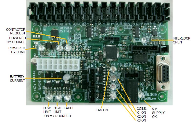
Function of LEDs, on a board level BMS controller.
The BMS controller has multiple LEDs to report its status.
| Name
| Color
| Function
|
| V+Load
| Red
| On if BMS is receiving power from the load (e.g.: motor controller)
|
| V+Source
| Amber
| On if BMS is receiving power from the source (e.g.: charger)
|
| ContReq
| Green
| On if BMS is receiving a request to turn on the contactors (e.g.: ignition line)
|
| Ibatt
| Red = discharging
Green = charging
| On if there's battery current; gets brighter with more current
|
| LLIM
| Blue
| On if BMS is driving the Low Limit line to ground
Note that polarity is programmable (ON = battery is fully discharged, or ON = battery is OK)
|
| HLIM
| Amber
| On if BMS is driving the High Limit line to ground
Note that polarity is programmable (ON = battery is fully charged, or ON = battery is OK)
|
| FLT
| Red
| On if BMS is driving the Fault line to ground
Note that polarity is programmable (ON = fault, or ON = OK)
|
| Fan
| Blue
| On if BMS is driving the Fan
|
| K1
| Amber
| On if BMS is driving the coil of precharge relay K1
|
| K2
| Red
| On if BMS is driving the coil of positive contactor K2
|
| K3
| Green
| On if BMS is driving the coil of negative contactor K3
|
| 5V
| Green
| On if the internal 5 V supply is OK
|
| I-lock
| Red
| On if the 2 pins of the Interlock connector are not shorted together
Note that polarity is programmable (shorted = OK, or open = OK)
|
The BMS controller includes hardware to drive contactors between the battery and the load.
The contactors can be controlled through the CAN bus. If not controlled through the CAN bus, the contactors can be controlled with the dedicated Contactors line (such as from the vehicle's Ignition line).
If the BMS controller sees a problem with the contactors, with isolation from the chassis, or with the load, it enters a Fault State.
In the Fault State, the BMS controller does not drive the contactors.
Contactors flowchart.
In the process of turning on contactors, a Lithiumate BMS with an HVFE performs a set of 6 tests to ensure that:
- the battery pack fuse is not blown
- the precharge relay does make contact
- the precharge relay is not permanently welded closed
- the positive contactor does make contact
- the positive contactor is not permanently welded closed
- the negative contactor does make contact
- the negative contactor is not permanently welded closed
- there is continuity in the precharge resistor
- the load capacitance is presence
- there is no short circuit in the load
It does so without the need for contactors with feedback switches.
The BMS constantly checks for the following areas of concern:
- Driving off while plugged in
- Interlock is tripped
- Communication fault with a bank or cell
- Charge over-current (with respect the CCL: Charge Current Limits, nominal and peak)
- Discharge over-current (with respect the DCL: Discharge Current Limit, nominal and peak)
- Over-temperature fault (temperature of the cell boards, taken while the balancing load is off)
- Under voltage (time averaged by the Cell voltage averaging time constant)
- Over voltage (time averaged, as above)
Should any of them (other than interlock activation) last longer than the Fault Delay, the BMS controller will go into a Fault state.
(Activation of the interlock input results in an immediate fault.)
For example, for discharge current, all of the following delays apply, one after the other:
- Current sampling, which is done every 1 s, so it can be 0 to 1 s, depending of the timing between a current pulse and the sampling time
- Current integral delay, which depends on the value of the discharge current with respect to the Nominal DCL and the Peak DCL:
- One second if the discharge current is at I = Nominal DCL setting + 10 * (Peak DCL setting - Nominal DCL setting)
- Five seconds if the discharge current is at I = Nominal DCL setting + 2 * (Peak DCL setting - Nominal DCL setting)
- Ten seconds if the discharge current is at the Peak DCL setting
- Twenty seconds if the discharge current is at I = Nominal DCL setting + 0.5 * (Peak DCL setting - Nominal DCL setting)
- One hundred seconds if the discharge current is at I = Nominal DCL setting + 0.1 * (Peak DCL setting - Nominal DCL setting)
- Infinite if the discharge current is at the Nominal DCL setting
- Fault delay, which by default is 10 s, though it can be set between 0 and 25 s
For example, for low cell voltage, all of the following delays apply, one after the other:
- Cell board scanning, which is done every 1 s, so it can be 0 to 1 s, depending of the timing between a voltage dip and the scanning time
- Cell voltage time averaging delay, which depends on the value of the lowest cell voltage before the dip, its value during the dip, and the Cell voltage averaging time constant (whose value is 25 s nominal, though it can be set between 0 and 255 s):
- Infinite if the lowest cell voltage is at the Min value and stays there
- Immediate if the lowest cell voltage had been at the Min value and it drops below that value by any minute amount
- Equal to the Cell voltage averaging time constant if the lowest cell voltage had been at Vnormal, and the dip is at Vdip, and (Vmin - Vdip) / (Vnormal - Vdip) = 1 / e
- Fault delay, which by default is 10 s, though it can be set between 0 and 25 s
If revs before 1.10, interlock fault is subject to the fault delay just as all other faults.
If revs before 1.05, the Cell voltage averaging time constant is fixed at 30 s.
If revs before 0.98, the CCL and DCL used a single limit each (no Peak limit).
The BMS also may perform the following tests (programmable) when turning on the contactors:
- No battery voltage
- High voltage B- leak to chassis
- High voltage B+ leak to chassis
- Contactor K1 shorted
- Contactor K2 is shorted
- Contactor K3 shorted
- No precharge
- Open K2
- Excessive precharge time
- EEPROM stack overflow
Should any of these tests fail, the BMS controller will go into a Fault state immediately.
The BMS also detects:
Should that occur, the BMS controller will go into a Fault state immediately.
Once in the Fault state, the BMS controller:
- will activate the FAULT output line
- will place a fault code on the CAN bus
- if so programmed, it will turn off the contactors
It is the responsibility of the customer to make sure that the rest of the system reacts to this fault state, to protect the battery.