These are installation instructions for cell boards in this case:
Large cylindrical cells
Warning.
Li-Ion batteries are dangerous!
Wear safety glasses.
Do not allow conductive objects (tools, solder...) to come into contact with cells or Cell Board
Do not touch more than one battery connection at the same time
Good technique
Unfortunately, we do not have the resources to teach all of our clients proper assembly procedures, which are essential for a succesful project.
What we can do is to pass along this info to you:
Prepare a Cell Board for pair of cells in series in that bank
Prepare 1 Positive End Cell Board, 1 Negative End Cell Board, and the number of Mid-bank Cell Boards shown in the table below
Number of cells in the bank
Cell boards
Mid-bank*
Positive
Negative
3
0
1
1*
4
0
1
1
5
1
1
1*
6
1
1
1
7
2
1
1*
8
2
1
1
9
3
1
1*
10
3
1
1
11
4
1
1*
12
4
1
1
13
5
1
1*
14
5
1
1
15
6
1
1*
16
6
1
1
*)
For N cells, where N is even, you need n/2-2 "mid-bank" Cell Boards
For N cells, where N is odd, you need (n+1)/2-2 "mid-bank" Cell Boards, and only 1/2 of the negative board is used
Even number of cells
Assign the Cell Boards to the cells:
All the Cell Boards will be mounted on the same side of as the bank's most positive and most negative terminals
Assign the positive end Cell Board to the 2 most positive cells
Assign the negative end Cell Board to the 2 most negative cells
Assign the mid-bank Cell Boards to the remaining pair of cells
Orient the Cell Board properly DO NOT CONNECT BACKWARDS!
The ring terminal that is mounted directly to the Cell Board (labeled 'B-' on the PCB) goes to the negative terminal of the most negative cell in the pair
The ring terminal that is mounted on a short red wire (labeled 'B+' on the PCB) goes to the positive terminal of the most positive cell in the pair
The ring terminal that is mounted on a long yellow wire (labeled 'BM' on the PCB) goes to either terminal on the opposite side of the cells (the bus bar that connects those terminals together)
The electronic components go towards the cell, the LED towards you
Place a Cell Board on the most negative terminal of its pair of cells
Remove the nut from the cell's terminal, keeping the power connection in place
Place the 'B-' ring terminal (mounted directly to the Cell Board) onto that terminal stud
Put the nut back on and secure it
Connect the Cell Board to either one of the mid point terminals of its pair of cells (on the opposite side of the cells; they're connected together)
Touch that terminal with the 'BM' ring terminal (mounted on the long yellow wire)
The LED will blink twice, repeated a total of 3 times
If the LED doesn't blink when first connected, DISCONNECT THE CELL BOARD IMMEDIATELY
If you installed the board backwards and removed it immediately, once connected properly it may appear to work correctly; however, it may be damaged and drain its cell
Test a Cell Board with a current meter in series with one of its power terminals; after the blinking stops there should be no measurable current drain
If the Cell Board draws measurable current after the blinking stops, or it it reports the wrong voltage, the Cell Board is damaged: replace it
If the Cell Board was connected properly, and yet the LED doesn't blink, please see the cell troubleshooting page
Remove the nut from one of the 2 cells' terminal, keeping the power connection in place
Place the 'BM' ring terminal (mounted on the long yellow wire) onto that terminal stud
Put the nut back in and secure it
Connect the Cell Board to the most positive terminal of its pair of cells
Touch that terminal with the 'B+' ring terminal (mounted on the short red wire)
The LED will blink twice, repeated a total of 3 times
If the LED doesn't blink when first connected, DISCONNECT THE CELL BOARD IMMEDIATELY; see above for info
Remove the nut from that cell's terminal, keeping the power connection in place
Place the 'B+' ring terminal (mounted on the short red wire) onto that terminal stud
Put the nut back in and secure it
Repeat with the other cells in a bank
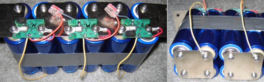
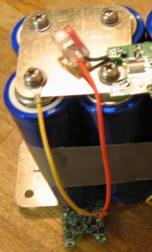
Cell boards mounted on a 6S2P battery of large cylindrical cells: top (left) detail of bottom (right).
If the bus bar extends below the cell board, add insulation on the bus bar to prevent shorts.
Odd number of cells
Proceed as above, except for the negative end Cell Board
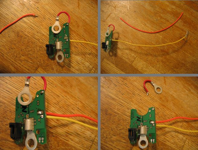
Prepare the negative end Cell Board
Cut off the orange wire
Cut a 18 AWG wire (preferably orange, but any color but red or black will do), same length as the yellow wire
Insert the wire from the component side, into the pad with the largest hole (labeled 'CM')
Solder the wire on the opposite end of the board
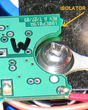
The ring terminal that is mounted on a short red wire (labeled 'B+' on the PCB) is not used: cut the wire or isolate the terminal.
Negative end board preparation with odd number of cells.
Assign the negative end Cell Board to the most negative cell (even though the board can handle 2 cells, it will only be used for 1 cell)
The negative end Cell Board will be mounted on the same side of as the bank's most negative terminal (on the opposite side as all the other boards)
Orient the negative end Cell Board properly DO NOT CONNECT BACKWARDS!
The ring terminal that is mounted directly to the Cell Board (labeled 'B-' on the PCB) goes to the negative terminal of the cell
The ring terminal that is mounted on a long yellow wire (labeled 'BM' on the PCB) goes to the positive terminal of the cell
Place the negative end Cell Board on the most negative terminal of its cell
Remove the nut from the cell's terminal, keeping the power connection in place
Place the 'B-' ring terminal (mounted directly to the Cell Board) on the negative terminal stud
Put the nut back in and secure it
Connect the Cell Board to the positive terminal of its cell (on the opposite side of the cell)
Remove the nut from the positive terminal of that cell, keeping the power connection in place
Place the 'BM' ring terminal (mounted on the long yellow wire) onto that terminal stud
Put the nut back in and secure it
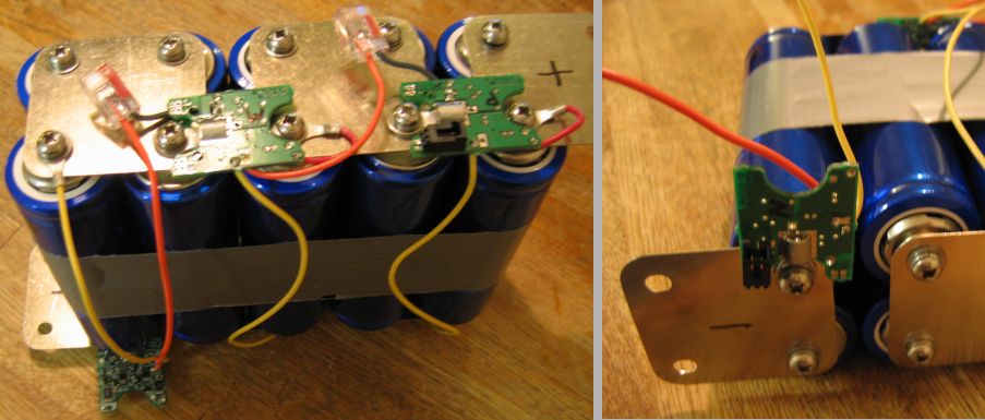
Cell boards mounted on large cylindrical cells (odd number of cells): positive side (left), negative end (right)
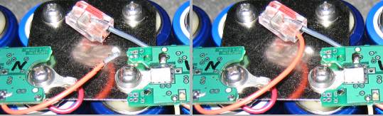
Cell Board communication wires installation
In betweem each pair of adjacent Cell Boards, the orange wire from the most negative of the 2 Cell Boards is connected to the splice at the end of the gray wire from the most postive of the 2 Cell Boards.
Even number of cell boards
Point the gray wire towards the negative terminal of the cell
Route the orange wire along the power bus bar between cells, and then to the gray wire in the adjacent Cell Board
If the orange wire is too long, cut it shorter, so that it ends at the splice on the gray wire
Strip the end of the orange wire 0.4" (1 cm)
Insert the orange wire in an open slot in the splice at the end of the gray wire, push all the way in
If required, secure the orange wire in place (use wire ties; do not twist it around the red wire or the bus bar)
In particularly noisy installations, you may need to use shielded cable; Before using this solution, first follow the noise abatement procedures, which usually are sufficient to eliminate problems due to noise pick-up, without the need for shielded cable
Cut and strip orange wire (left) and instert in splice (right).
Odd number of cell boards
Proceed as above, except for the negative end Cell Board
Use the wire you added to the negative end cell board to connect to the splice at the end of the gray wire in the adjacent cell board
Communication wire for negative end cell board, odd number of cells.