logo

Lithiumate™ Manual

index install install_cable_sensor

Install - Cable mount current sensors

Installations and wiring instructions for the 2CS0xx0K series, 50 to 600 A, bidirectional, cable mounted current sensors

cable-mounted current sensor
back to topGood technique

Unfortunately, we do not have the resources to teach all of our clients proper assembly procedures, which are essential for a succesful project. What we can do is to pass along this info to you:

back to topTermination instructions

Because the desired cable length is not known a priori, the sensor comes with an unterminated cable and a connector kit. Use these instructions to terminate the cable in the field.

Schematic of cable mount current sensor
  • Install the current sensor and the BMS controller in their final positions
  • Measure and cut the current sensor's cable to an appropriate length
  • Unclad the cable end 1 inch, careful not to nick the wires
  • Remove the shield foil
  • Strip all 4 wires 1/8 inch
  • Crimp 4 C-Grid female sockets to the wires
  • Slip the sockets in the 4-conductor C-Grid connector, until they snap in place
    1. Red
    2. Green
    3. White
    4. Black and shield bleed wire (uninsulated)
Assembly diagram of cable mount current sensor

For replacement parts, see the parts list

back to topInstallation instructions
  • Slip the battery power cable through the opening in the current sensor, so that, when discharging, current flows into the side that has the signal cable (note that the arrow printed on the label is the direction of discharging current)
  • Connect the signal cable to the BMS controller (4-pin, black connector)
Direction of current in current sensor

For your reference, current flow is:

  • On positive lead, charging: towards battery
  • On positive lead, discharging: away from battery
  • On negative lead, charging: away from battery
  • On negative lead, discharging: towards battery
Wire size anchor

The biggest wire that fits in the opening in the cable mounted current sensor can carry far more current than the sensor can detect. So, if your cable doesn't fit, either the current sensor is undersized for your application (e.g.: you're using a 500 A current sensor in a 5000 A application), or the wire is oversized for the application (e.g.: you're using a wire for 2000 A average when it only carries 100 A average).

In an EV, it can be counterproductive to use 1/0 AWG for a wire that carries 100 A average current: the energy you saved by reducing power losses may be lost in needlessly carrying all that extra copper around.

Regardless, if the cable is too large for the opening on the sensor, you may:

  • Install the current sensor on a copper bus bar, and connect the battery cable to the bus bar, or
  • Strip the cable, run the copper strands inside the sensor, isolate the strands with heat shrink tubing, or
  • Find a different current sensor, with a larger opening (however, please note that we are not able to guarantee the suitability of any current sensor other than the ones we sell)
Current sensor on a bar
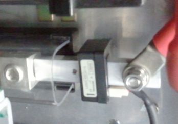
Bar-mounted current sensor
back to topConfiguration

Configuration instructions for a load current sensor.
Configuration parameters for our standard cable mounted current sensors (middle section of the table).

back to topTwo sensors

We never suggest that someone should use both a 600 A and a 50 A current sensor. If you use the automatic quote generator, and answer its questions, it tells you to use just the 600 A current sensor for both the charger current and the load current. It does not tell you to use 2 separate current sensors.

Having said that, there is a way for this BMS controller to use both a 600 A and a 50 A current sensor, but it's a bit complicated.

It entails powering both sensors from the EXT CURRENT SENSOR connector, but wiring the output of the 600 A sensor to the EXT CURRENT SENSOR connector, and the output of the 50 A sensor to the white CONTROL connector.

The 600 A load current sensor will be bidirectional (discharging and regen), while the 50 A current sensor will be unidirectional (charging).

You must not splice the 2 sensors outputs together: they will fight each other.

Instructions:

  • Mount the 600 A sensor on the cable between the battery and the load
  • Mount the 50 A sensor on the cable between the battery and the charger, making very sure that it is oriented on the cable so that the flow of charger current is in the same direction as the arrow printed on the sensor's body
  • Connect both red wires to pin 1 of the 4-pin EXT current connector
  • Connect both green wires to pin 2 of the 4-pin EXT current connector
  • Connect both black wires and both shields to pin 4 of the 4-pin EXT current connector
  • Connect the signal wire (white) of the 600 A load current sensor pin 3 of the 4-pin EXT current connector
  • Connect the signal wire (white) of the 50 A charger current sensor to pin 6 of the white Control connector
  • Configure the BMS to work with the 600 A load sensor
    • Input: EXT CURR SNSR
    • Gain: 150 A/V
    • Offset: ~4096 (use the actual reading when there is 0 load current)
  • Configure the BMS to work with the 50 A source sensor
    • Input: SRC
    • Gain: 12 A/V
    • Offset: ~0 (use the actual reading when there is 0 source current)
Schematic to use two cable mounted current sensors
Example of two cable mounted current sensors.
Gui screenshot
Screenshot of configuration tab in GUI, while there's 0 current through sensors.
e-logo

© 2008~2024 Elithion™, LLC. All rights reserved, except where noted by CC mark. Page published on Jul 19 2013.
The Elithion brand and the 'ə' (upside down 'e') logo are Trademarks of Elithion LLC. Graphic design by morninglori


In this page: