|
|
index  install install_cell_board_pouch_single install install_cell_board_pouch_single
Install - single pouch cell board
Installation and wiring instructions for single cell boards for pouch cells

A cell board WILL be damaged if you do any of these common mistakes.
A DAMAGED CELL BOARD MAY DRAIN ITS CELL!
 Li-Ion batteries are dangerous!
- Wear safety glasses.
- Do not allow conductive objects (tools, solder...) to come into contact with cells or Cell Board
- Do not touch more than one battery connection at the same time
Unfortunately, we do not have the resources to teach all of our clients proper assembly procedures, which are essential for a succesful project.
What we can do is to pass along this info to you:
The Lithiumate is a distributed BMS: each cell board MUST be mounted directly on its cell.
Do not attempt to use it as a centralized BMS: cell boards off to the side.
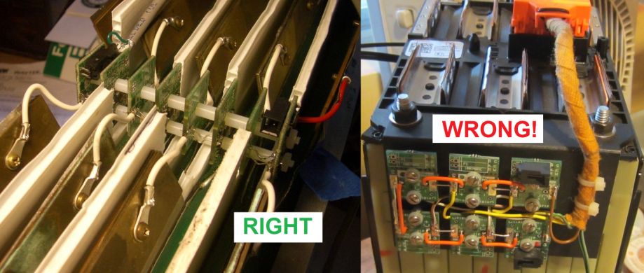
Right (cell boards directly on cells) and wrong way (cell boards off to the side) to use cell boards for pouch cells.
Attempt to use it as a centralized BMS will result in improper operation: poor noise immunity, low accuracy, no temperature sensing.

Stack of 4 pouch cells.
Stack the pouch cells in a battery, flat side to flat side.
- Single series string (1P) batteries: arrange the cells with alternating polarity, so that the '+' terminal of one cell is adjacent to the '-' terminal of the next cell.
- Multiple cells placed in parallel (such as 2P, 3P, etc.): arrange the cells in a parallel block all facing the same way, and arrange the blocks with alternating polarity, so that the '+' terminal of one block is adjacent to the '-' terminal of the next block.
Top view of cell stacks: 4S1P (left) and 4S2P (right).
The overall '+' and '-' terminals are at the top left and top right, respectively.
Retain the cells in an enclosure that prevents the cells from expanding when they are charged.
Not doing so will allow the cells to expand and delaminate, reducing their life time.
For example, use 2 plates, one on either end of the stack, using threaded rods to retain their distance against pressure from the cells.
The stack above uses 1 positive end (reverse connector), 2 mids (short version), 1 negative end (reverse connector).
The stack is dropped in the space between cell tabs; the 5 wire loops (4 of which can be seen in the left picture) or 5 copper tabs (right picture) are clamped to the cells' tabs.
1) Figure out the pitch of the stack: the spacing between adjacent cell boards.
Assuming that the cells are directly against each-other:
- Single series string (1P) batteries: this is just the thickness of the cell
- Multiple cells placed in parallel (such as 2P, 3P, etc.): this is just the thickness of the cell times the number of cells in parallel
If there are spacers between cells, their thickness must be added in.
2) Calculate the length of the spacers between adjacent cell boards:
spacer length = stack pitch - cell board thickness = stack pitch - 0.062" = stack pitch - 1.6 mm
Plan the number, placement and orientation of the cell boards.
- For N cells in series (regardless of how many cells in parallel) you need:
- 1 positive end cell board
- N-2 mid bank cell boards
- 1 negative end cell board
- Draw the layout of the cells, as seen from above, including the tabs and marking the '+' and '-' terminals
- Draw the cell boards exactly in the middle of the tabs
- Mark the cell boards:
- For the most positive cell, mark its cell board as a positive end cell board
- For the most negative cell, mark its cell board as a negative end cell board
- Mark the other cell boards as mid bank boards
- For all cell boards, mark 'B+' on the edge closest to the positive tab of its cell, and 'B-' on the edge closest to the positive tab
- Mark the terminal taps:
- On the most positive end, draw a line between the 'B+' mark and the '+' tab of the cell
- On the most negative end, draw a line between the 'B-' mark and the '-' tab of the cell
- Elsewhere, draw a 'Y' shaped line between each pair of as of yet unconnected 'B+' and 'B-' marks and the midpoint between the '+' and '-' tabs of the cells (a total of N-1 lines)
- Mark the communication wires wires:
- Behind each 'Y' shaped line, draw a line between adjacent cell boards (a total of N-1 lines)
Top view of cell stacks with cell boards stacks, before the cell tabs are folded: 4S1P (left) and 5S1P (right).
Green areas are the N cell boards.
Light blue lines are the N-1 communication wires.
Dark blue lines are the N+1 terminal taps.
Yellow areas are the spacers.
Top view of cell stacks with cell boards stacks, after the cell tabs are folded to form the series connection: 4S1P (left) and 5S1P (right).
Dark blue lines are the N+1 terminal taps, clamped to the cell tabs.
Translate your plan into actual cell boards.
- Place actual cell boards to match your plan, to confirm the plan (orient the cell boards so that the hole closest to the edge will be closest to the cells)
- For the end cell boards note where the connector (if any) ends up
- If the connector is inside the stack, and ends up in the way of an adjacent cell boards, plan to use a short mid cell board there, to leave space for the connector
- To convert a standard mid board to a short one:
- Score the PCB with a knife, along the row of small holes, on both sides of the PCB
- Grab the short 1/3 of the PCB (the one without components) with a pair of pliers
- Place the other 2/3 of the PCB on a table, so that row of holes is along the edge of the table
- Rotate the pliers up slowly, until the 1/3 of the PCB snaps off
- If the connector is outside of the stack, make sure there is enough space in the battery box for it and its mate
- You can always replace a right angle connector with a straight connector, or vice versa, or move a connector on the other side of the board
- If you do, be careful to solder pin 1 of the connector (marked by a triangle on the connector plastic body) into pin 1 on the PCB (square pad)
- Plastic spacers to separate the cell boards, # 4 (or 3 mm) ID, 0.2" max O.D., such as these:
- For 0.125" (3.1 mm) stack pitch: 1/16" (0.062", 1.6 mm) Nylon washers
- For 0.187" (4.7 mm) stack pitch: 1/8" (0.125", 3.1 mm) Nylon spacers
- For 0.250" (6.3 mm) stack pitch: 3/16" (0.187", 3.1 mm) Nylon spacers
- For 0.312" (7.9 mm) stack pitch: 1/4" (0.250", 6.35 mm) Nylon spacers
- For 0.375" (9.5 mm) stack pitch: 5/16" (0.312", 7.9 mm) Nylon spacers
- For 0.437" (11.1 mm) stack pitch: 3/8" (0.375", 9.5 mm) Nylon spacers
- For 0.500" (12.7 mm) stack pitch: 7/16" (0.437", 11.1 mm) Nylon spacers
- For 0.562" (14.3 mm) stack pitch: 1/2" (0.500", 12.7 mm) Nylon spacers
- For 0.625" (15.9 mm) stack pitch: 9/16" (0.562", 14.3 mm) Nylon spacers
- For 0.687" (17.5 mm) stack pitch: 5/8" (0.625", 15.9 mm) Nylon spacers
- For 0.750" (19.0 mm) stack pitch: 11/16" (0.687", 17.5 mm) Nylon spacers
- For 0.812" (20.6 mm) stack pitch: 3/4" (0.750", 19 mm) Nylon spacers
- For 0.937" (23.8 mm) stack pitch: 7/8" (0.875", 22.2 mm) Nylon spacers
- For 1.062" (27.0 mm) stack pitch: 1" (25.4 mm) Nylon spacers
- Flat, insulating plastic washers, # 4 (or 3 mm), such as these:
- Threaded 4-40 (or M3) rods, such as these:
- 4-40 (or M3) nuts, such as these:
- Solid, 24 AWG bare wire, such as these:
- For spacing between terminals above 1.5 inches (40 mm), copper or brass sheet material, such as these:
- brass strip, 0.025" thick, 1/4" wide; x 1 ft long (ideal)
- copper foil, 0.020" thick, 1/2" wide, 100 ft roll
- copper sheet, 0.020" thick, 2" x 3 ft
- brass foil, 0.020" thick, 1/2" wide, 50 ft roll
- brass sheet, 0.020" thick, 2" x 3 ft
- For spacing between terminals above 3 inches (80 mm), insulated hook-up wire, such as these:
For each stack:
- Cut 2 threaded rods to length (make them longer than the stack it you will use them to mount the stack to the battery case)
- Place 2 insulating washers and 2 nuts at one end of the rods
- Orient all cell boards so that the hole closest to the edge is at the bottom
- Insert rods in the positive end cell board
- If the overall positive terminal of the battery is on the top left or bottom right corner (when looking at the tabs): insert the rods on the side without components
- If the overall positive terminal of the battery is on the top right or bottom left corner (when looking at the tabs): insert the rods on the side with components
- Place spacers on the rods, on the other side of the cell board from the side that faces the nuts
- While the list of spacers above is very comprehensive, you may need to stack multiple spacers and / or washers to achieve the desired cell board pitch
- Insert a mid board on the rods, facing the opposite way from the positive end cell board:
- If the positive end cell board component side faces this mid board: insert the rods on the side of the mid board with components
- If the positive end cell board component side faces away from this mid board: insert the rods on the side of the mid board without components
- If the positive end cell board has a connector that would be in the way of the mid board, use a short mid board (see above for instructions on making one)
- Repeat with the remainder of the mid cell boards for this stack, alternating the orientation of the mid board, and using spacers between cell boards
- Finally, insert the negative end cell board
- Place 2 insulating washers on the rods
- Place 2 nuts on the rods
- Tighten the nuts
Check the cell board stack:
- Confirm that the number of cell boards matches the number of cells in series in the stack
- Confirm that the 'B+' pad of the positive cell board will face the overall '+' terminal of the cell stack
- Confirm that the 'B-' pad of the negative cell board will face the overall '-' terminal of the cell stack
- Confirm that for each cell board its 'B+' pad faces the 'B-' pad of the adjacent cell boards, and vice versa
- Confirm that all the cell boards bottom edges are at the same level (none are sticking out)
- Confirm that the distance between adjacent cell boards matches the pitch of the cell stack
- Confirm that the overall distance between the positive and negative end cell boards is appropriate for the cell stack
Add communication wires between adjacent cell boards (N-1 wires for N cell boards):
- On the positive end board, insert a straight, bare wire in the 'C-' pad, into the 'C+' pad of the next cell board
- Solder the wire to the pads
- Cut off excess wire
- Repeat with a new wire, between the 'C-' pad of the 2nd board, to the 'C+' pad of the next cell board
- Repeat with the rest of the cell boards, until you reach the 'C+' pad of the negative end cell board
DO NOT CONNECT ANY WIRES BETWEEN DIFFERENT BANKS!
So far the assumption is that the distance between cell boards is fairly short, so it's OK for the wires to be uninsulated.
If, however, the distance is significant, use insulated wire (solid, not stranded)
In this step you will add the connections ("terminal taps") on the cell boards that in the final step will go from the cell boards to the cell tabs.
The way terminal taps are done depends on the spacing between terminals (there is some overlap, where it is up to you to choose a method):
- Up to 2.5 inches (60 mm): wire loops
- Between 1.5 and 5 inches (40 to 130 mm): tabs
- Above 3 inches (80 mm): wires and tabs
For short distances between cell tabs, the same wire that connects adjacent cell boards together can double as terminal taps.
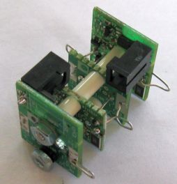
Click to enlarge.
The wires will start from from pads on the cell boards, and extend 1/2" (13 mm) into the tabs, and be clamped to the tabs.
The assumption is that the cell board stack will be placed half way beween the cell tabs.
The wire is doubled over, so it needs to be twice as long as that distance.
The length of these wires is:
length = T + P + 0.55" = T + P + 14 mm
where T is the distance bewteen the cell tabs (not the center-to-center spacing), and P is the cell board pitch.
Add terminal taps between adjacent cell boards and at the 2 ends (N+1 wires for N cell boards):
- Cut N+1 wires, to the length defined above
- Fold the wires in half
- On the positive end board, insert one end of a wire in the 'B+' pad, and lay the other end on the same pad; solder both ends to the pad
- Repeat on the 'B-' pad of the negative end cell board
- Insert a wire in the 'B-' pad of the positive end board, and the 'B+' pad of the 2nd cell board; solder both ends to the pads
- Insert a wire in the 'B-' pad of the 2nd cell board, and the 'B+' pad of the 3rd cell board; solder both ends to the pads
- Repeat with the remainder of the boards
For medium distances between cell tabs, for terminal taps use tabs extending from the cell boards.
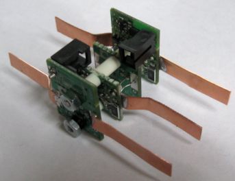
Click to enlarge.
Use 1/4" strips of copper or brass.
The length of these tabs is:
length = 0.5 * T + 0.2 * P + 0.2" = 0.5 * T + 0.2 * P + 5 mm
where T is the distance bewteen the cell tabs (not the center-to-center spacing), and P is the cell board pitch.
Add tabs for terminal taps between adjacent cell boards and at the 2 ends (N+1 tabs for N cell boards):
- Cut N+1 tabs, to the length defined above
- On the 2 end boards, solder two tabs on the wide, rectangular pads marked 'B+' and 'B-', extending outwards
- On eack pair of adjacent mid boards, on the same side as the communication wire between the 2 boards, on just one of the 2 boards, solder a single tab on the wide, rectangular pad next to the communication wire (a total on N-3 tabs)
Add terminal wires between adjacent cell boards (N-1 wires for N cell boards) (note that these wires are physically parallel to the communication wires between adjacent boards):
- Solder a wire between the 'B-' pad of the positive end board, and the the 'B+' pad of the 2nd cell board
- Solder a wire between the 'B-' pad of the 2nd cell board, and the 'B+' pad of the 3rd cell board; solder both ends to the pads
- Repeat with the remainder of the boards
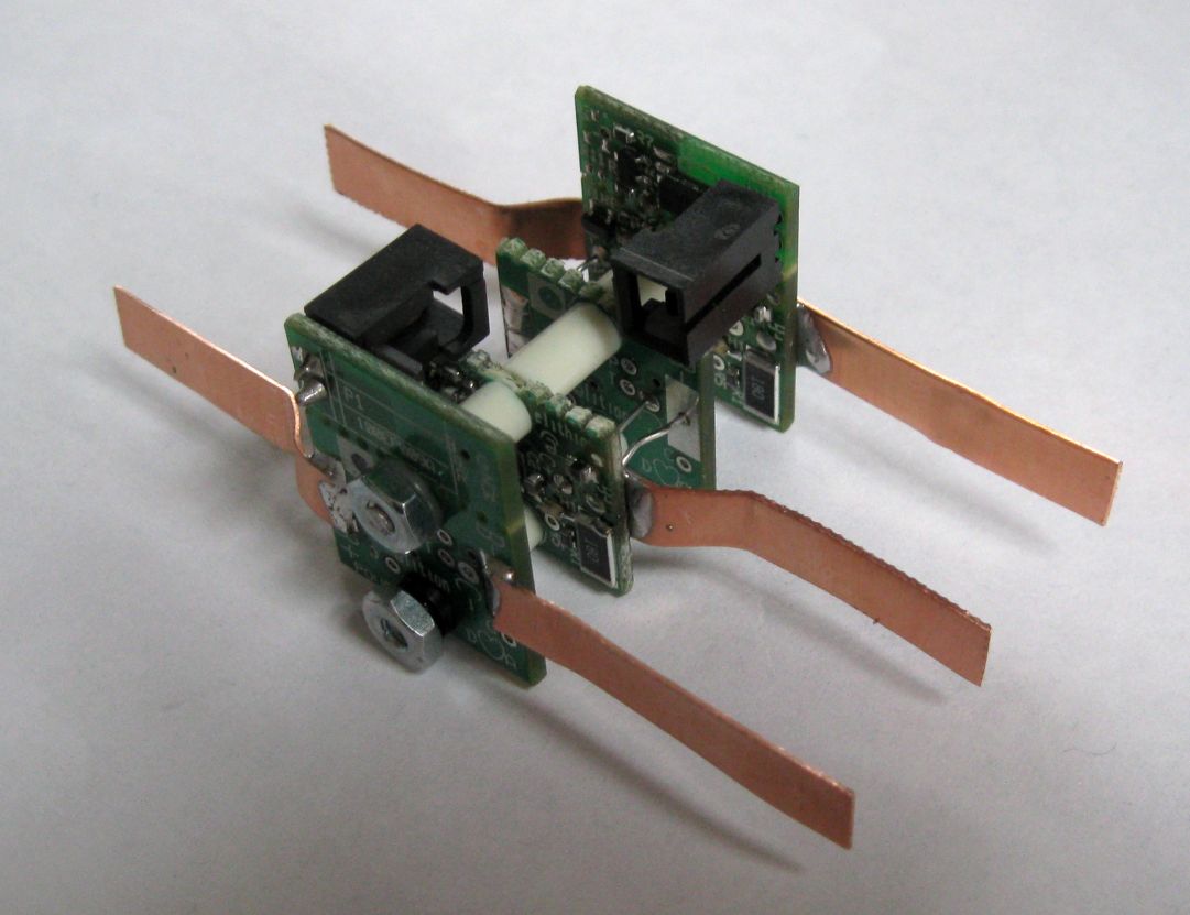
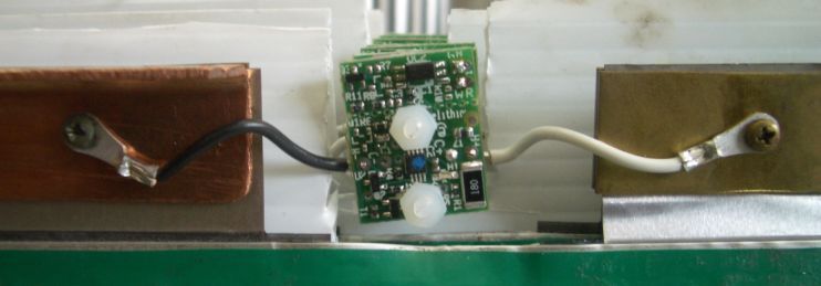
For large distances between cell tabs, for terminal taps use wires extending from the cell boards with tabs at the end.
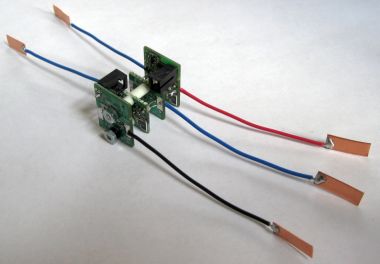
Click to enlarge.
The length of the wires is:
length = 0.5 * T + P - 0.1" = 0.5 * T + 0.2 * P - 3 mm
where T is the distance bewteen the cell tabs (not the center-to-center spacing), and P is the cell board pitch.
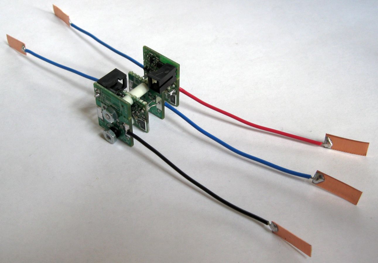
Add wires and tabs for terminal taps between adjacent cell boards and at the 2 ends (N+1 sets for N cell boards):
- Cut N+1 wires, to the length defined above: 1 black, one red, and N-1 blue
- Cut N+1 tabs, 1/4" x 3/4" (6 x 19 mm)
- Strip one end of the wires 0.1" (3 mm) and solder it to the end of a tab; do not let the solder flow more than 0.2" (5 mm) from the edge
- Strip the other end of the red and black wires 0.1" (3 mm)
- Strip the other end of the blue wires P + 0.2" (5 mm)
- On the positive end board, insert the red wire in the pad marked 'B+' and solder
- On the negative end board, insert the black wire in the pad marked 'B-' and solder
- On the positive end board, starting from the outside of the stack, insert the blue wire in the pad marked 'B-', then thread into the pad marked 'B-' of the 2nd cell board (note that this wire is physically parallel to the communication wire between these 2 boards); solder the wire to both pads
- Repeat with the remainder of the boards

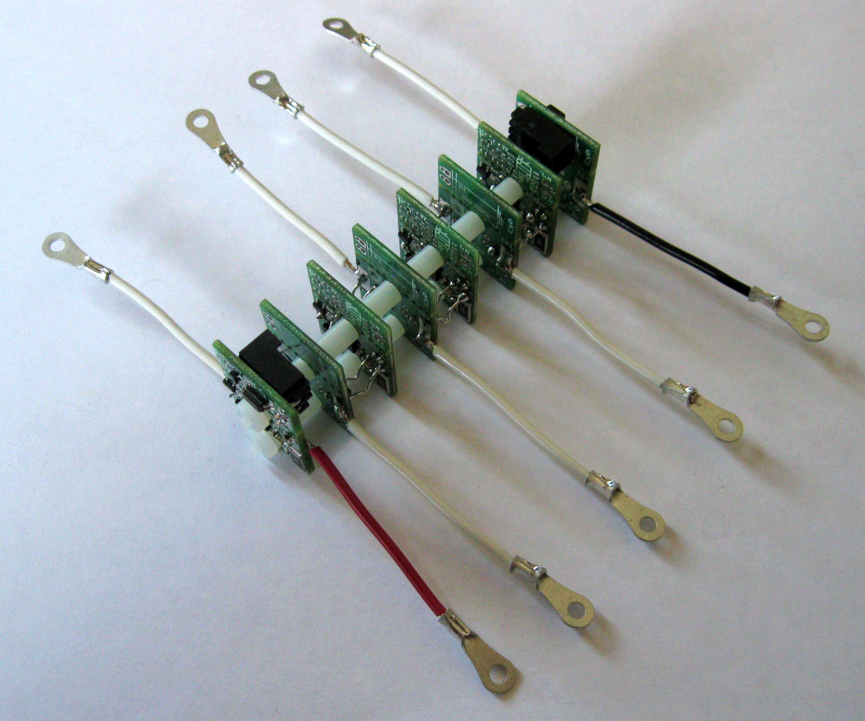
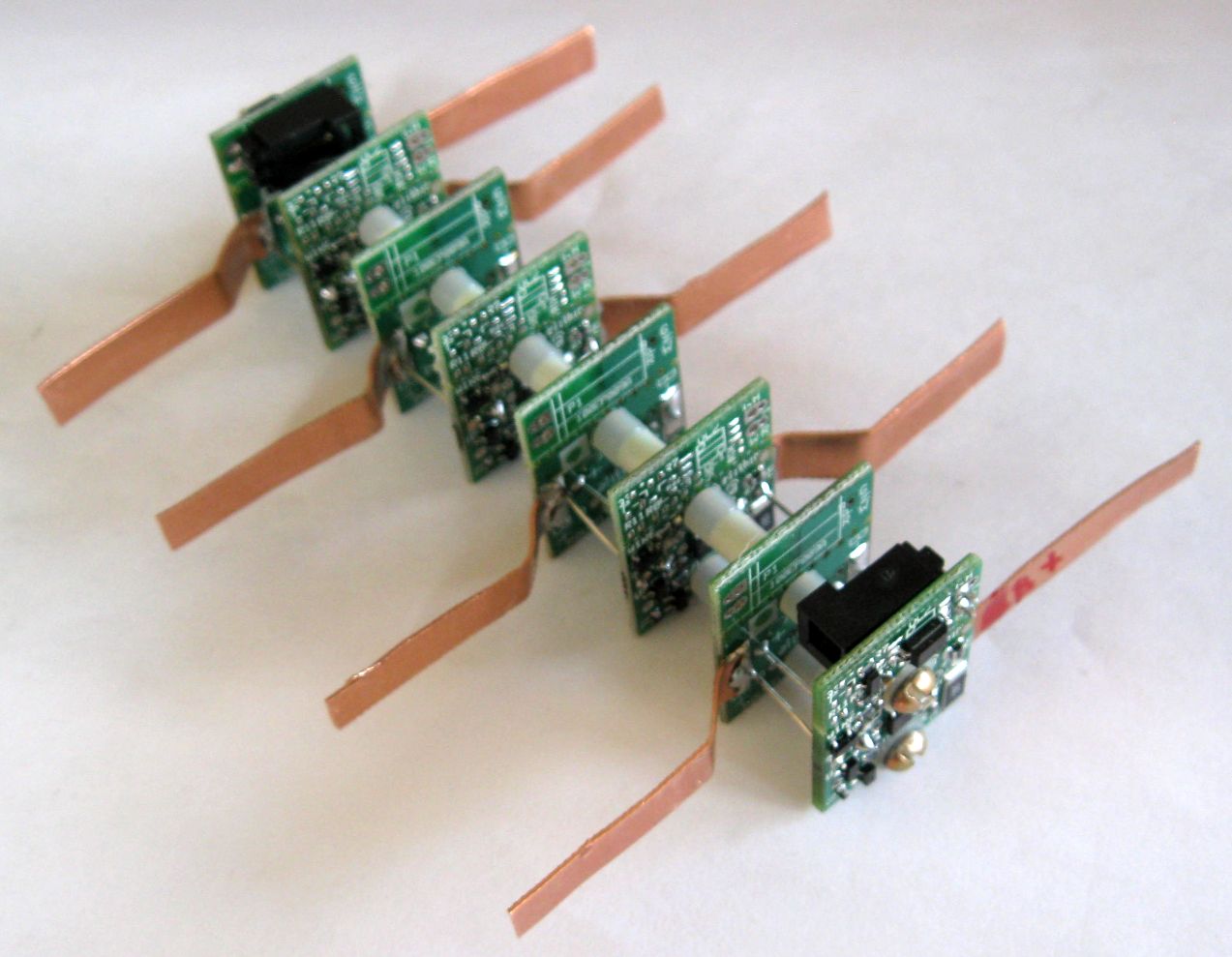
Example of a stack for 8 cells in series, 0.65" pitch.
Click to enlarge.
Check the cell board stack:
- Confirm that the number of straight wires directly between cell boards is N-1
- Confirm that the straight wires directly between cell boards alternate between sides
- Confirm that the number of bent wires between the cell boards to the cells is N-1
- Confirm that the number of bent wires between the cell boards to the cells are on the same side of the cell boards as the straight, direct wires
- Confirm that there is 1 bent wire out of the 'B+' pad of the positive end cell board
- Confirm that there is 1 bent wire out of the 'B-' pad of the negative end cell board
- Confirm that distance between the end-to-end distance of the terminal taps is the distance between the cell tabs, plus about 1" (25 mm)
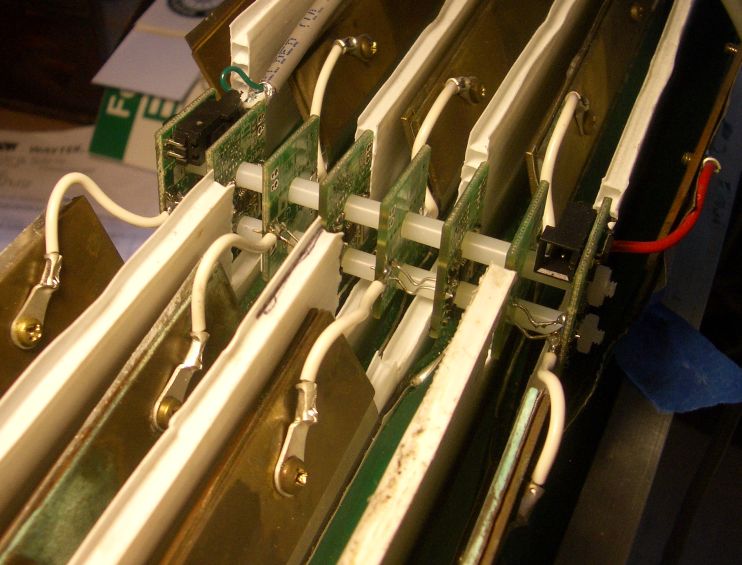
Cell boards placed between cell tabs.
- Drop the cell board stack on the cell stack, in the area between tabs
- Careful to orient the cell board stack correctly: do not reverse it or you'll blow up the cell boards!
- Careful not to make unintentional connetions with the cells
- Fold each pair of adjacent cell tabs to make the series connection, inserting the corresponding terminal taps between the cell tabs
- Clamp the cell tabs together, using one of various suggested methods:
- You may keep the cell tabs flat, or you may fold them a few times, as one does with a coffee bag
- You may use metal spring clips (isolated on the outside) or especially built plastic clips, to keep the tabs together (this is a fast method)
- Use of plates as force spreaders is recommended if using clips
- You may cut holes in the tabs and in retaining plates, and fasten them together with bolts, washers and nuts (this is labor intensive, and it is very easy to do a short circuit with a bolt)
- After the 1st connection, as you make each additional connection, note that the LED on the newly connected cell boards flashes 2 times (repeated 3 times)
- If the LED doesn't blink when first connected, DISCONNECT THE CELL BOARD IMMEDIATELY
- If you installed the board backwards and removed it immediately, once connected properly it may appear to work correctly; however, it may be damaged and drain its cell
- Test a Cell Board with a current meter in series with one of its power terminals; after the blinking stops there should be no measurable current drain
- If the Cell Board draws measurable current after the blinking stops, or it it reports the wrong voltage, the Cell Board is damaged: replace it
- If the Cell Board was connected properly, and yet the LED doesn't blink, please see the cell troubleshooting page
- Clamp the battery terminals to the 2 cell tabs at the end of the stack, at the same time clamping the corresponding terminal taps
Example of a clip clamping together pouch cell tabs, in a 2P battery (4 tabs: 2 from the previous cells, 2 from the next cells).
- Install the the controller in its final position
- Prepare the communication harness for this bank
- Plug the communication harness to the controller in one of the 'BANK' sockets:
- Start from the socket labeled 'BANK 0' for the most positive bank, then use the next available socket: 'BANK 1', 'BANK 2', etc
- If using multiple batteries in parallel, see the banking page
- Connect the communication harness to the Cell Boards in that bank:
- If using plugs:
- Plug the connector with red and black wires to the plug marked 'C+', on the Positive End Cell Board
- Plug the connector with white and green wires to the plug marked 'C-', on the Negative End Cell Board
- If not using plugs:
- Positive End Cell Board: solder the red and black wires to the 2 pads in the corner: red to the round pad, black to the square pad (in the corner)
- Negative End Cell Board: solder the white and green wires to the 2 pads in the corner:white to the round pad, green to the square pad (in the corner)
The labels on the PCB mean:
- B = black wire (ground)
- G = Green wire (ground)
- N = negative cell board
- P = positive cell board
- R = red wire (Rx positive board)
- W = White wire (Tx negative board)
Repeat with the remaining banks

|
|