logo

Lithiumate™ Manual

index gui

GUI application

Lithiumate Pro Graphics User Interface

The Lithiumate GUI (Graphics User Interface) application runs on a Windows or Linux computer
and allows you to configure, monitor and test a Lithiumate BMS
running software revision 2.00 or higher.

back to topRequirements
back to topWindows Installation

Note: do not confuse the installer and the installed application:

  • The installer is called "LithiumateProGUI.application" and will be in your download folder; you can delete it after you're done with it
  • The installed application is called "LithiumateProGUI" and will be in Start menu / All programs / Elithion / Lithiumate GUI

(Sorry about the complexity, but this is a Microsoft .NET thing, and we have no control over it.)

Note: the computer that you will be using to talk to the Lithiumate requres Internet access only when installing the application; afterward, Internet access is desirable (to get updates) but not required

Application vs installer icons
  1. With Internet access, download the Windows Lithiumate GUI installer to the hard drive of a Windows PC
  2. With Internet access, run the installer ("LithiumateProGUI.application") to install the actual application ("LithiumateProGUI") on your computer
  3. Connect the computer to the Lithiumate BMS using an RS232 cable, or an RS232 to USB adapter
  4. Wait for Windows to install the driver for the USB device
  5. Power-up the BMS master
  6. Start the Lithiumate GUI application, "LithiumateProGUI", installed on your computer (NOT the "LithiumateProGUI.application" installer)
No Internet access anchor

Since you're reading this, you do have Internet access, but maybe the computer you'll use to run the GUI doesn't have Internet access.
If so, you can use a USB drive to transfer the GUI from this computer to the other one.

  1. On a computer that does have Internet access, plug in a flash drive into a USB port
  2. Go to the Download page in Elithion's server
  3. Download the LithiumateProGUI.application file to the flash drive
  4. Create a folder in the flash drive called Application Files and open it
  5. Click the "Application Files" link in the download page to go to the Application Files page
  6. Download the latest LithiumateProGUI_1_0_0_##. file (the one with the highest number) into the Application Files folder in the flash drive
  7. Unplug the flash drive from the USB port
  8. Plug in the flash drive into a USB port of the computer that will run the GUI
  9. Open the LithiumateProGUI.application file in the flash drive
  10. Install the GUI application in that computer
back to topLinux Installation
NOT FOR RASPBERRY PI
  1. Preliminary requirements: You will need root privileges on the computer to enable access to the (USB) serial communications device and to install library dependencies. The Lithiumate GUI has been tested with success on x86 and x86_64 Debian Wheezy and Ubuntu 14.14 LTS, as well as 32 bit ARM Debian Wheezy. Also, Mono, a .NET runtime for Linux, is needed.
  2. Install the necessary dependencies in the terminal with the command
    sudo apt-get install mono-devel libmono-2.0-1.
    If those specific packages are not available for your system, get Mono from the Mono Project's Linux installation page.
  3. Download the Linux binary for the GUI.
  4. Open a terminal and change to the directory containing the download.
  5. Extract the archive:
    $ tar zxvf LithiumateProGUI.tar.gz
  6. This should produce a .exe file. If that succeeds, try running it (from terminal):
    $ ./LithiumateProGUI.exe
  7. You may keep the output executable anywhere you desire; there is no requirement to install it system-wide.
  8. Running: Connect the computer to the Lithiumate BMS using an RS232 cable, or an RS232 to USB adapter.
  9. Identify the devfs file Linux has registered for your cable. Typically it is
    /dev/ttyUSB0
    —you can find out by issuing the command
    dmesg|tail
    after inserting the cable. In the output you will see a line like
    [ 3337.343040] usb 1-1: FTDI USB Serial Device converter now attached to ttyUSB0
    which identifies ttyUSB0 as the device.
  10. Give yourself permissions to read and write to the cable device by running
    sudo chmod 0777 /dev/ttyUSB0
    for the device file before starting the GUI application. Note that permissions need to be granted with every insertion of the cable.
  11. Power-up the BMS master.
  12. Start the Lithiumate GUI application. It should identify and connect to the the serial cable device in seconds. The status line at the top of the application will show the status of search for the device.
  13. Depending on the Linux distribution and libmono library versions, the application may run in a graphically degraded state, but should function correctly otherwise.
back to topGeneral

NOTE: When using the GUI application, to see detailed information on a given item, hover over that item.

Map of the user interface anchor

The application offers:

Map of the GUI application
Screen tabs anchor

The application offers:

The application offers many tabbed screens:

Screens in  the GUI application
gui_map
back to topScreen
Meters screen anchor

This screen reports the basic status of the BMS through 3 analog meters, a digital meter and 6 indicators, in very simple terms, in order not to overwhelm the unsophisticated user.

  • Meters
    • Battery SOC
    • Battery current
    • Battery voltage
    • kWh readout
  • Indicators
    • AC power
    • Ignition power
    • Charging OK
    • Discharging OK
    • Warning
    • Fault
Meters screen
Status screen anchor

This screen displays the entire present status of the BMS.

The status items are grouped into:

  • BMS: state of the BMS itself: power, time, current sensors, outputs
  • PACK: state of the pack: SOC, voltage, current
  • CELLS: state of banks and cells: voltages, temperatures, resisatnces, balance, communication
Graph screen anchor

This screen graphs the status of the BMS.

  • Plot of certain parameters over time
  • Histogram of the present value of certain parameters

The parameters are shown are selectable.

Configure screens anchor

There are 10 screens under the Configuration tab and they are:

  • Basic - This screen has buttons for cell chemistry and a box to enter the cell amp hour rating
  • Cell-V - This screen is for entering the information for SOC VS Voltage
  • Cell-R - This screen is for entering the information for Cell Resistance VS SOC and Cell Resistance VS Temperature
  • Battery - This screen is for entering the capacity of the battery and if there are strings in parallel
  • Measure - This screen has the following:
    • Button for Relearn - to have the BMS relearn how many cell boards there are
    • Cell Board indicators for total cell boards
    • Cell boards/bank - lists the number of cell boards configured and number of cell boards seen
    • Current Sensors - This is used to set-up both the Source and Load current sensors
    • Selector for pack voltage to come from the HVFE if the HVFE is present
    • Measurement section - to select if IR compensation is to be used, to set the averaging time constant and the measurement period.
  • Protect - This screen is for entering the protection limits for the cells and battery as well as the Fault values.
  • Balance - This screen is for setting the parameters for balancing of the pack
  • Evaluate - This screen is for the following:
    • SOC estimate - to select to not use the SOC points on the Cell-V screen and to set the minimum current level
    • Capacity - to select to calculate the capacity and the minimum cell voltage for the capacity calculation
    • SOH estimate - set the minimum %SOH below which the BMS issues a warning
    • Isolation Test - various settings for the isolation test
  • Control - This screen has settings for the digital inputs, digital outputs, analog outputs and the contactors
  • Communicate - This screen has settings for the parameters for the CAN and RS232 communications
BMS test screens anchor

There are three screens under the test tab.

They are:

  • BMS test
    • Digital outputs - force on or off
    • Analog outputs - set values
    • Indicators for various values in the BMS
  • Terminal - Classic text based interface with the BMS
  • CAN bus - For using the PEAK PCAN dongle with the BMS

After done forcing the outputs, click the "Restore automatic control" button, else the battery is not protected.

New screen anchor

This screen displays the history of the changes with the GUI and the BMS.

The screen is divided into:

  • New features of this GUI
  • New features of the BMS
  • Tips

back to topMenus
File anchor

The "File" menu lets you:

  • Configuration: read or write the configuration settings, from and to the BMS and from and to the computer's hard drive
  • Capture: log BMS data to a file
  • Quit
File menu
View anchor

The "View" menu lets you select a screen,

View menu
Tools anchor

The "Tools" menu lets you:

  • Set or enter a password
  • Upgrade the BMS master's software
  • Reset the BMS master
  • Reset the comm port
  • Clear a fault
  • Reset the plot
Tools menu
Options anchor

The "Options" menu lets you:

  • Set which temperature is shown: cells or cell boards
  • Set the way the cells are numbered
  • Set the meter ranges
  • Set the trip meter mode
  • Set the way middle meter to either current or power
  • Set the BMS to hold the peak values
  • Set the histogram to sorted
Options menu
Help anchor

The "Help" menu lets you:

  • Go to this manual
  • Contact tech support
  • See info about the GUI application
Help menu
back to topInfo items

At the top of the window, the GUI gives additional information

  • An alert line, to warn if the battery is not protected
  • An information line about the BMS master and the COM port
  • A flag that blinks during communication to the BMS master
back to topSoftware upgrade
  • GUI application: If there are new revisions of the GUI software, it will automatically ask you permission to upgrade when you first start it, as long as the computer has an internet connection.
  • BMS master software:
    • Software revision 2.xx: upgrade instructions
    • Software revision 1.xx: contact us for upgrade options and costs
  • BMS master software, software revision 1.xx: contact us for upgrade options and costs
back to topLogging

You can capture the data into a log that can be opened by a spreadsheet program such as Excel.

  1. Select the File / Capture / File menu
  2. Enter a file name and browse for a locations
  3. When ready, click File / Capture / Start
  4. When done, click File / Capture / Start
  5. Find the CSV file in your hard drive and open it
  6. When prompted, specify that the delimiters is the tab character (and only the tab character)
Setting up the spreadsheet
Click picture to enlarge

CSV file set-up in OpenOffice Calc
Lithiumate Pro anchor

For the Lithiumate Pro, the data are:

Point Real time Power-up time Asrc Alod Apack Vpack SOC DOD Loads BalVtg BalCause IoState Flags Bnk0 Bnk1t Bnk2 Bnk3 Bnk4 Bnk5 Bnk6 Bnk7 Bnk8 Bnk9 Bnk10 Bnk11 Bnk12 Bnk13 Bnk14 Bnk15 CCL CCLcause DCL DCLcause WarnFlags FltFlags MissBanks MissBank# MissCells -0 Vmin VminNo VminAvg Vavg Vmax VmaxNo VmaxAvg Tmin TminNo Tavg Tmax TmaxNo Rmin RminNo Ravg Rmax RmaxNo Rpack Nmonit Vmonit Tmonit TmonitOff Rmonit Smonit Cell 0 Cell 1 Cell 2
12 15:38:45 000:02:33:02 -16.9 0 -16.9 55.2 100 0 0 3.45 1 SrcPwr
10 FF FF FF FF FF FF FF FF FF FF FF FF FF FF FF 86 100
HiVtg
0
0
3.45 16 3.44 3.45 3.48 11 3.47 18 16 18 20 4 0 15 0 0.3 16 0.8 0 3.45 26 0.2
15 3.45 3.45 3.45
Sequential number of the record. If you selected a rate is 1 sec / point, then this is the relative number of seconds Time of the clock of the computer that runs the GUI Time since the BMS was powered-up or reset.
days:hours:
minutes:seconds
Current seen by current sensor that is active when the BMS is powered by the Vsource supply input [A]. Positive = discharge Current seen by current sensor that is active when the BMS is powered by the Vload supply input [A]. Positive = discharge Total pack current [A] Positive = discharge 
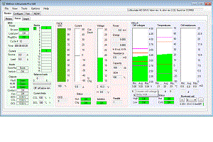
Total pack voltage [V] State of Charge [%] Depth of Discharge [Ah] Number of cell boards whose balance load is on Cell voltage [V] above which its cell board turns on the balance load.
4.55 V = balancing is off
Code for why balancing is off;
0: Cell board too hot
1: Voltages all within delta bal vtg
2: Voltages below min bal vtg
3: Rest period
4: Not powered by the source
Input / output state flags:
SrcPwr: BMS powered by Vsource
LoadPwr: BMS powered by Vload
IntLock: Interlock input tripped
WireContReq: there's a request to turn on the contactors from the Contactor Request input
CanContReq: there's a request to turn on the contactors from the CAN bus
HLIM: Cannot charge
LLIM: Cannot discharge
Fan: The fan is running
General flags:
EEWR: Writing to the non-volatile memory
ManOvrd: BMS in manual override
RelayFlt: Fault while turning on the contactors
CommErr: Bank communication error
WaitRst: Waiting for the cell boards to recover
FAULT: the BMS issued a fault
K1: Contactor K1 is on
K2: Contactor K2 is on
K3: Contactor K3 is on
For Bank 0 (Hex value)
00: looking for cells
01~1F: OK, number of cells seen
80: comm error: did got the same message back
81~9F: config error: seeing more cells than set:
82: seeing 2 cells
83: seeing 3 cells
etc
FE: comm error: scrambled message
FF: comm error: there is no communication
(or, configured for 0 cells)
Same, for Bank 1 Same, for Bank 2 Same, for Bank 3 Same, for Bank 4 Same, for Bank 5 Same, for Bank 6 Same, for Bank 7 Same, for Bank 8 Same, for Bank 9 Same, for Bank 10 Same, for Bank 11 Same, for Bank 12 Same, for Bank 13 Same, for Bank 14 Same, for Bank 15 Charge Current Limit [%]
100: no charging limit
50: max charge current = 1/2 of Peak Charge Current configured setting
0: charging not allowed
Code for why charging current is limited:
Pack voltage too low
Pack voltage too high
Cell voltage too low
Cell voltage too high
Charg. temp. too high
Charg. temp. too low
Disch. temp. too high
Disch. temp. too low
Charg. current peak
Disch. current peak
Power up delay
Fault
Discharge Current Limit [%]
100: no discharging limit
50: max charge current = 1/2 of Peak Discharge Current configured setting
0: discharging not allowed
Code for why charging current is limited:
Pack voltage too low
Pack voltage too high
Cell voltage too low
Cell voltage too high
Charg. temp. too high
Charg. temp. too low
Disch. temp. too high
Disch. temp. too low
Charg. current peak
Disch. current peak
Power up delay
Fault
Warning flags:
LowVtg: low cell voltage
HiVtg: high cell voltage
OvrChgCur: charge over-current
OvrDchCur: discharge over-current
Cold: low temperature
Hot: high temperature
Isol: isolation ground fault
Fault flags:
Plug&Drive: Powered by Vload and Vsource at the same time: vehicle driving off while still plugged in
I-lock: the Interlock is active
BnkComm: Bank communication fault
ChgOvrCur: excessive charging current
OvrDchCur: excessive discharging current
Hot: a cell is too hot
LowVtg: a cell voltage is too low
HiVtg: a cell voltage is too high
Number of banks not reporting:
0: OK
1: One of the banks is not reporting
Number of one of the banks that are not reporting:
2: bank 2 is not reporting, though there may be others as well
Number of cell not reporting:
0: OK
1: One of the cells is not reporting
(not used) Minimum cell voltage [V] Number of one of the cells that has that lowest voltage Time average of the minimum cell voltage [V] Average of all cell voltages [V] Maximum cell voltage [V] Number of one of the cells that has that highest voltage Time average of the maximum cell voltage [V] Minimum cell board temperature [°C] Number of one of the cell boards that has that lowest temperature Average of all cell cell board temperatures [°C] Maximum cell board temperature [°C] Number of one of the cell boards that has that highest temperature Minimum cell resistance [mΩ] Number of one of the cell boards that has that lowest resistance Average of all cell cell board resistances [mΩ] Maximum cell resistance [mΩ] Number of one of the cell boards that has that highest resistance Total pack resistance [mΩ] Through the GUI, you can select a particular cell to monitor.
Number of that cell.
Voltage of the monitored cell [V] Temperature of the monitored cell [V] Temperature of the monitored cell taken the last time its balancing load had been off [°C] Resistance of the monitored cell [mΩ] State of the monitored cell :
00: missing cell
07: all readings OK, resistance value is calculated
0F: all readings OK, resistance value is not calculated, load is on
40: no readings, resistance value is not calculated
46: all readings OK except for voltage, resistance value is not calculated
47: all readings OK, resistance value is not calculated
4F: all readings OK, resistance value is not calculated, load is on
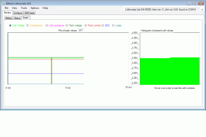
For the most positive cell (normally cell #0, but can be configured for a different number in the GUI):
One of the 3 readings, as selected in the Graph tab of the GUI:
- Voltage [V]
- Temperature [°C]
- Resistance [mΩ]
Same, for the next cell Etc.
Lithiumate Lite anchor

For the Lithiumate Lite, the data are:

  • Time - Time since the BMS was powered [hhh:mm:ss]
  • Achg - Current seen by the 30 A charger current sensor [A]
  • Alod - Current seen by the 900 A load current sensor [A]
  • Apack - Net battery current (total of the two values above) [A]
  • Vpack - Pack voltage
  • SOC - State Of Charge [%]
  • DOD - Depth Of Discharge [Ah]
  • Loads - Number of balancing loads on [-]
  • BalVtg - Cell voltage below which no balancing will occur [V]
  • BalCause - Code for the reason why balancing is or is not occurring
    • 0: Cell board too hot
    • 1: Voltages all within delta balance voltage
    • 2: Voltages below min balance voltage
    • 3: Cool down period
    • 4: Not powered by the AC
  • IoState - State of the inputs; left to right, "1" means:
    • the Fan is on
    • the LLIM is set
    • the HLIM is set
    • there is a CAN contactor request
    • there is a hard wire contactor request
    • the interlock is tripped
    • there is power from the Ignition
    • there is power from the AC line
  • Flags (ExtFlags) - left to right, "1" means:
    • (not used)
    • (not used)
    • (reserved: HvVtgAbs)
    • (reserved: RelayFlt)
    • (reserved: DigOvrRd)
    • (reserved: AnlOvrRd)
    • (reserved: EeChange)
    • (reserved: LoggedIn)
  • BankStat0 - Code indicating the state of bank 0 (Elithion IP)
  • BankStat1 - Same, but for bank 1
  • BankStat2 - Same, but for bank2
  • BankStat3 - Same, but for bank3
  • BankStat4 - Same, but for bank4
  • BankStat5 - Same, but for bank5
  • BankStat6 - Same, but for bank6
  • BankStat7 - Same, but for bank7
  • BankStat8 - Same, but for bank8
  • BankStat9 - Same, but for bank9
  • BankStat10 - Same, but for bank 10
  • BankStat11 - Same, but for bank 11
  • BankStat12 - Same, but for bank 12
  • BankStat13 - Same, but for bank 13
  • BankStat14 - Same, but for bank 14
  • BankStat15 - Same, but for bank 15
  • CCL - Charge Current Limit [%]; 100 % = no limit
  • CCLcause - Code for why the CCL is limited:
    • 0: No limit
    • 1: Pack voltage too low
    • 2: Pack voltage high
    • 3: Cell voltage low
    • 4: Cell voltage high
    • 5: Temperature high for charging
    • 6: Temperature too low for charging
    • 7: Temperature high for discharging
    • 8: Temperature too low for discharging
    • 9: Charging current peak lasted too long
    • 10 = A: Discharging current peak lasted too long
    • 11 = B: Power up delay (Charge testing)
    • 12 = C: Fault
    • 13 = D: Contactors are off
  • DCL - Discharge Current Limit [%]; 100 % = no limit
  • DCLcause - Code for why the DCL is limited. See CCLcause table, above
  • WarnFlags - Flags indicating a warning; left to right, "1" means:
    • Isolation fault
    • SOH is low
    • hot temperature
    • cold temperature
    • over discharge current
    • over charge current
    • high voltage
    • low voltage
  • FltFlags - Flags indicating a fault; left to right, "1" means:
    • over voltage
    • under voltage
    • over temperature
    • discharge overcurrent
    • charge overcurrent
    • communication fault with a bank or cell
    • interlock is tripped
    • driving off while plugged in
  • MissBanks - Number of banks that are not communicating
  • MissBank - The number of one of the banks that is not communicating
  • MissCells - Number of cells that are not communicating
  • MissCell - The number of one of the cells that is not communicating: 0 = most positive, 1 = next to the most positive, etc.
  • Vmin - Instantaneous voltage of the cell with the lowest voltage [V]
  • VminNo - Number of the cell with the lowest voltage [-]; 0 = most positive, 1 = next to the most positive, etc.
  • VminAvg - Time average of the IR compensated minimum voltage [V]
  • Vavg - Instantaneous average of all the cell voltages (not time averaged) [V]
  • Vmax - Instantaneous voltage of the cell with the highest voltage [V]
  • VmaxNo - Number of the cell with the highest voltage [-]; 0 = most positive, 1 = next to the most positive, etc.
  • VmaxAvg - Time average of the IR compensated maximum voltage [V]
  • Tmin - Mininum cell board temperature [°C]
  • TminNo - Number of the coldest cell board; 0 = most positive, 1 = next to the most positive, etc.
  • Tavg - Average cell board temperature (not time averaged) [°C]
  • Tmax - Maximum cell board temperature [°C]
  • TmaxNo - Number of the hottest cell board; 0 = most positive, 1 = next to the most positive, etc.
  • Rmin - Resistance of the cell with the lowest resistance [mΩ]
  • RminNo - Number of the cell with the lowest resistance [-]; 0 = most positive, 1 = next to the most positive, etc.
  • Ravg - Average cell resistance (not time averaged) [mΩ]
  • Rmax - Resistance of the cell with the highest resistance [mΩ]
  • RmaxNo - Number of the cell with the highest resistance [-]; 0 = most positive, 1 = next to the most positive, etc.
  • Rpack - Pack total resistance [mΩ]
  • Nmonit - Number of the cell being monitored at the time (selected through the GUI, in the Status screen); 0 = most positive, 1 = next to the most positive, etc.
  • Vmonit - Voltage of the cell being monitored at the time [V]
  • Tmonit - Temperature of the cell being monitored at the time [°C]
  • TmonitOff - Temperature of the cell being monitored at the time, the last time the balancing load was off [°C]
  • Rmonit - Resistance of the cell being monitored at the time [mΩ]
  • Smonit - Code for the state of the cell being monitored at the time (Elithion IP)
  • Cell 0 - Data for cell 0 (the most positive cell), depending which item waws selected in the histogram in the GUI application at the time: voltage [V] or temperature [°C], or resistance [mΩ]
  • Cell 1 - Same, but for cell 1
  • Cell 2 - Same, but for cell 2
  • ...
  • Cell n - Same, but for cell n, the last cell used
e-logo

© 2008~2024 Elithion™, LLC. All rights reserved, except where noted by CC mark. Page published on May 09 2018.
The Elithion brand and the 'ə' (upside down 'e') logo are Trademarks of Elithion LLC. Graphic design by morninglori


In this page: