|
|
index  install install_inline_sensor install install_inline_sensor
Install - In line current sensors
Installations, wiring and programming instructions for the 2CS00xxL series, 5 A and 20 A, bidirectional, in-line current sensors

Unfortunately, we do not have the resources to teach all of our clients proper assembly procedures, which are essential for a succesful project.
What we can do is to pass along this info to you:
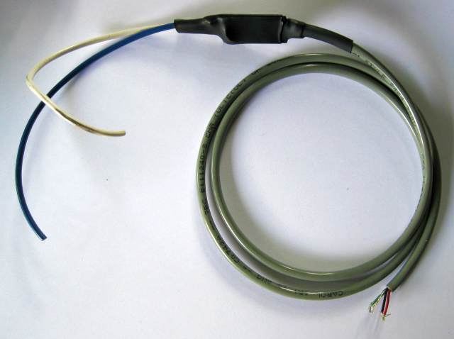
The sensor comes with 2 wires for current sensing:
- Blue
- White (20 A sensor) or gray (5 A sensor)
Instructions:
- Select either one of the 2 wires between the source (charger) and the battery (typically, the red, positive wire is selected)
- Place the current sensor in a convenient location along that wire
- Open the connection in that wire, by either cutting it, or disconnecting one end of it
- Wire the current sensor in series of that open connection, to reconnect it through the current sensor, so that the charge current flows into the blue wire
- If placing it close to the charger, on the positive wire: connect the blue wire to the charger '+' output, and the other wire to the red wire going to the battery
- If placing it close to the battery, on the positive wire: connect the blue wire to the red wire going to the charger '+' output, and the other wire to the battery's '+' terminal
- If placing it close to the charger, on the negative wire: connect the blue wire to the black wire going to the battery, and the other wire to the charger '-' output
- If placing it close to the battery, on the negative wire: connect the blue wire to the battery's '-' terminal, and the other wire to the black wire going to the charger '-' output
The charge current must flow into the blue wire.
Any one of these 4 ways of connecting the sensor will work.
If the wires in your system are of a larger gauge than the wires on the current sensor, minimize losses by cutting the current sensor's wires relatively short
The sensor comes with an unterminated cable for power and reading.
- Red: +5 V
- Green: signal out
- Black: ground
- Braid: shield
- White: not used
Instructions:
- Cut the cable as appropriate
- Connect the cable to the white Control connector on the BMS controller.
- Red (+5 V): connect to +5V, pin 7 on the Control connector
- Green (signal): connect to SrcCur, pin 6 on the Control connector
- Black & braid (ground, shield): connect to Gnd, pin 1 on the Control connector
Configuration instructions for a source current sensor.
Configuration parameters for our standard in-line current sensors (last 2 items in the table).

|
|