logo

Lithiumate™ Manual

index reference app_notes hvfe_high_source_current_mod

HVFE high source current modification

HVFE modification instructions to use the high current sensor as a source current sensor.

These are instructions on modifying a remote front end to use its high current sensor (50 A, 100 A or 200 A) as a source current sensor instead of as a load current sensor.

In order to make this modification, you need to have good soldering skills, to make a small modification to the HVFE.

back to topApplicability

These instructions are applicable to remote HVFEs or BMS controllers with HVFE, with a high current sensor. They are also applicable if the HVFE has 2 current sensors, though the low current sensor will not be useable.

This modification requires that a cable mounted current sensor is used to measure the load current.

These instructions are applicable to the following part numbers:

  • HVFEs with high current sensor: 2HR0050, 2HR0100, 2HR0200
  • BMS controllers with HVFE with high current sensor: 2CN0050, 2CN0100, 2CN0200
  • HVFEs with 2 current sensors: 2HR0055, 2HR0070, 2HR0105, 2HR0120, 2HR0205, 2HR0220
  • BMS controllers with HVFE with 2 current sensors: 2CN0055, 2CN0070, 2CN0105, 2CN0120, 2CN0205, 2CN0220

These instructions are applicable to remote HVFEs with hardware rev E. The rev level is the last letter (followed by 2 digits) in the part number, which is written on the 7-pin white connector.

These instructions are applicable to remote HVFEs with software rev 1.04 (07/06/10) and above, which was programmed into 2HRxxxxxExx and above.

back to topHardware mod
  1. If encased, open the case that contains the HVFE.
  2. Find the locations marked R36 and R37, next to the microprocessor (U4) and the large, silver capacitor (C16); there are no component in those locations, just pads
  3. Use a temperature controlled soldering iron, at low temperature, with a fine tip
  4. For each location, short the 2 pads together with a solder bridge; do not use too hot a soldering iron, or the solder will bead on each pad and not form a bridge if you wish, you can use a tiny, short piece of wire to ease the bridging
  5. If applicable, close the case back up
Modified HVFE
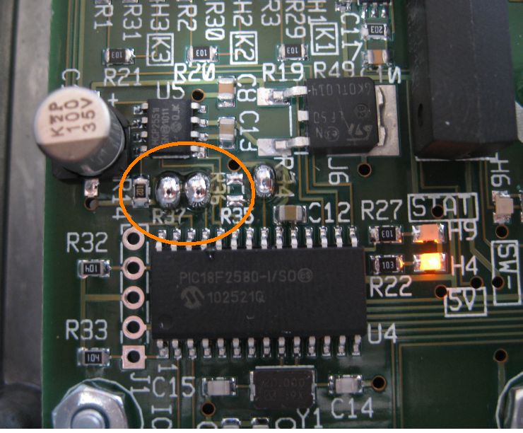
Solder bridges across R36 and R37.
back to topConfiguration
  1. On the terminal, for the load current select the cable mounted current sensor (Home / Set-up / Current sense / Load current / Current sensor / Input / On cable / Enter)
  2. Go to the System Status screen (Home / Status / System) to confirm that:
    • The Source Current reading is from the HVFE through the CAN bus
    • The Load Current reading is from the cable mounted current sensor
e-logo

© 2008~2024 Elithion™, LLC. All rights reserved, except where noted by CC mark. Page published on Jul 19 2013.
The Elithion brand and the 'ə' (upside down 'e') logo are Trademarks of Elithion LLC. Graphic design by morninglori


In this page: