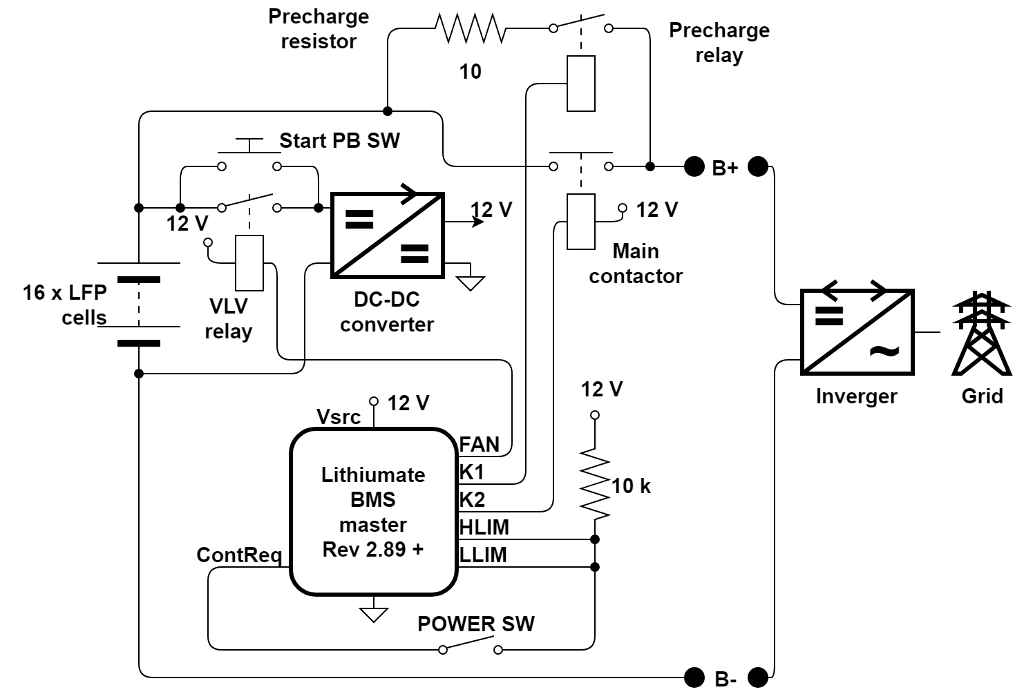
The Elithion BMS may be used in a 48 V battery for use with a Magnum inverger ("invertyer / charger").
By reading this page you acknowledge that you understand that these application notes are just suggestions, and that you will not hold Elithion responsible for their accuracy or appropriateness in you application, and that Elithion is not responsible for the fact that other manufacturers change their products in a way that may make these suggestions no longer applicable.
The Magnum inverger does not offer the BMS a way to reduce the charging or discharging current.
Therefore, a different approach must be used.
Additionally, we want to solve the conundrum of how to power the DC-DC converter that powers the BMS:
- Powered directly from the string of cell (before the contactor):
the DC-DC converter will fully drain and damage the battery after a long perion of non use
- Powered after a contactor:
if the contactor is turned off, the BMS is no longer powered, so the battery cannot be turned on again: it requires human intervention
In a back-up system, constantly keeping the cell voltages at maximum will shorten their life;
we wish to avoid that, by reducing the top cell voltage;
that will reduce the effective capacity a bit, but will increase the life of the cells a lot;
for example, for LFP cells, let's limit the top voltage to 3.4 V
We want precharge between the battery and the inverger,
to prevent the damaging inrush in current to charge the capacitors in the inverger when the contactor is first turned on
Here's the plan:
- We power the DC-DC converter through a "Very Low Voltage" relay;
should any cell voltage reach an under-voltage fault level, the relay is opened, removing power to the DC-DC converter (and therefotre to the BMS);
- We rely on the inverger to attempt to keep the cell voltages of within range, by keeping the battery voltage within this range: 41.6 to 54.4 V;
assuming an ideal battery (equal capacity cells and a balanced battery), the cell voltages with be all equal and within the range of 2.5 to 3.4 V
- Otherwise (the inverger doesn't limit the voltage, the battery is unbalanced, or the cell capacity varies), the BMS must intervene
- If any cell voltage exceeds 3.5 V, HLIM is activated, which drives the helper relay
- Similarly, if any cell voltage drops below 2.4 V, LLIM is activated, which also drives the helper relay
- In either case, the helper relay removes power to the contactor request, which turns off the main contactor
- Should the battery be off for a long period, the DC-DC converter will drain the battery (because it's powered before the main contactor);
yet, as soon any cell voltage drops to 2.3 V, a fault occurs, the "Very Low Voltage" relay opens, and the DC-DC converter is disconnected

Interfacing the Magnum inverger and the Elithion BMS
Configure the inverger:
- Set the absorption and float voltages: 54.4 V (= ~3.4 V / cell)
- Set the low voltage cutoff voltage: 44.8 V (= ~2.8 V / cell)
The BMS software rev must be 2.89 or later.
Configure the BMS (assuming 16 LFP cells in series):
- Set the protection voltages (Configure / Protect tab):
- Vcell-OV: 3.6 V
- Vcell-max: 3.5 V
- Vcell-high: 3.35 V
- Vcell-low: 2.7 V
- Vcell-min: 2.5 V
- Vcell-UV: 2.3 V
- Set the SoC voltages (Configure / Cell-V tab):
- Vmax: 3.4 V
- Vhigh: 3.35 V
- Vlow: 3.0 V
- Vmin: 2.8 V
- SOC-high: 95 %
- SOC-low: 10 %
- Set the balance voltages (Configure / Balance tab):
- Minimum balance cell voltage: 3.35 V
- Set the control lines (Configure / Control tab):
- Uncheck "Contactor request reverse polarity"
- Check "HLIM reverse polarity"
- Check "LLIM reverse polarity"
- Uncheck "FLT reverse polarity"
- Uncheck "FLT as LV warning"
- Check "FAN as LV fault"


