
When connected to a simple test fixture, the Lithiumate HD Master can test itself.
The test fixture is powered from the AC and connected to the Lithiumate HD under test.
A Windows* computer running the Elithion Lithiumate GUI application is connected to the Lithiumate HD under test
Test results are reported by LEDs on the test fixture, and by a screen displayed by the terminal emulator application.
* Alternatively, any computer running a terminal emulator application such as PuTTY.
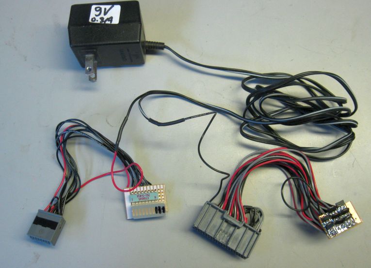
The test fixture consists of a wall mounted power supply, a small PCB assembly with a few components, and two connectors to mate to the HD master.
A Mini-USB cable is also required.
Circuit.
Example.
Set-up:
- Install the Elithion Lithiumate GUI on the Windows computer (if not a Windows computer, install a terminal emulator application, such as PuTTY)
- Connect a Mini-USB cable to the computer
- Connect the test fixture's power supply to AC power
- When done testing, remember to reload the configuration file back to the BMS
Extra preparation for non-virgin units (that have been configured once, such as field returns):
- Connect the HD master to the Mini-USB cable and to the test fixture
- Run the Lithiumate GUI application
- Save the present configuration onto a file on the computer's hard drive, because it will be deleted in the next steps
- Type H, 6, 6 on the computer to go to the force EEPROM screen
- Type TAB F F RETURN to clear the first EEPROM location
- Reset the BMS with the Tools / Reset BMS Menu (or press CTL-SHIFT-R); the unit will return to virgin conditions
Test:
- Connect the HD master to the Mini-USB cable and to the test fixture
- Run the Lithiumate GUI application
- Go to the Test / Terminal tab and click on the large text area on the left
- Type H, 6, 8 on the computer to go to the HD test program
- Check that the 7 LEDs in the test fixture alternate "|_|_|_|" and "_|_|_|_" (| = on, _ = off)
- Check that the terminal application screen alternates between "Result: _ _ ________ __" and "Result: R C 01234567 SX"
- If not, note which LED or which character is not alternating
- Disconnect the HD master from the Mini-USB cable and from the test fixture
If the test fails, use the following guide to determine the failure.
NOTE that the cause could be the test fixture (not the HD master).
If an LED does not alternate, use this table to determine a possible cause.
LED 1 is the one closest to the edge of the LED bar.
Note that the 3 LEDs at the opposite end of the LED bar are not used and remain off.
| LED
| Output
| Stays off
| Stays on
|
| 1
| Fault
| Open
| Shorted
|
| 2
| K3
| Open
| Shorted
|
| 3
| K2
| Open
| Shorted
|
| 4
| K1
| Open
| Shorted
|
| 5
| Fan
| Open
| Shorted
|
| 6
| LLIM
| Open
| Shorted
|
| 7
| HLIM
| Open
| Shorted
|
If an Character does not alternate in the screen, use this table to determine a possible cause.
| Character
| Function
| Stays '_'
| Stays as character
|
| R
| Fan PWM output fed into the Contactor Request input
| Fan PWM output open or grounded; Contactor Request input open or grounded
| Fan PWM output stuck high
Contactor Request input tied to a high voltage
|
| C
| CAN bus and termination
| Master thinks that the CAN bus is shorted
| Master thinks that the CAN bus is open / unterminated
|
| 0~7
| Bank TX output fed into RX input
| Bank TX output grounded or open, RX input open
| Bank RX input grounded
|
| S
| CCL analog output (pin 40) alternates between 2.5 V and 0 V
Fed directly into the Source current sensor input (pin 2)
| CCL analog output open, grounded
CCL D/A converter bad
Interlock reverse polarity checkbox not checked in GUI
| (not possible)
|
| X
| DCL analog output (pin 20) alternates between 3.0 V and 0 V
SOC output (pin 19) steady at 2.0 V
DCL and SOC analog outputs combined through two 100 k resistors and fed into the External current sensor input with a 20 k pull up to 5 V
Input (pin 22) alternates between 2.5 V and 1.0 V
| DCL analog output open, grounded
CCL D/A converter bad
DOC analog output open, grounded
SOC D/A converter bad
Interlock reverse polarity checkbox not checked in GUI
| DCL analog output grounded and SOC analog output tied to 5 V (or viceversa)
|