|
Current sensor installation
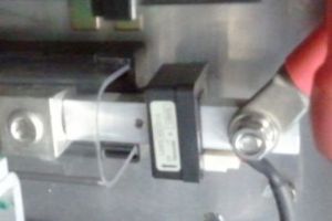
Install the load current sensor
The current sensor measures the battery current to any high voltage load connected to it (and back from it, in case of regen), whenever the BMS master is powered through its "Ignition 12 V" input. The load includes:
The current meter needs to see all of the current from all of the loads conneted to the pack; otherwise the ability of the BMS to calculate SOC will be reduced. Note that the charger current is not included in the list above. The BMS master measures the charger current, with a different current sensor, whenever the AC power is present. The load current sensor is installed anywhere along the path of all the battery current that occurs when the ignition is on:
If the pack uses cells in parallel or strings in parallel, watch out for a common mistake: putting the current sensor on a bus bar or power cable that carries only part of the battery current. The sensor must "see" all the battery current, If it is possibible that the ignition is on at the same time that the car is still plugged into the AC power, a problem could occur: if the load current sensor also sees the charger current (such as if it is installed on a bus bar inside the battery), the charger current would be counted twice, once by each sensor, resulting in errors in the SOC. To prevent that, either ensure that the ignition cannot be on when the car is plugged into the AC power, or place the load current sensor in a place that does not see the charger current,
Note that the load current sensor measures the battery current, not the motor current. The power cables carrying the battery current to the motor controller should be sized to carry the average current, yet handle the occasional peak current. When looking for the current carrying capability of wire, you will find a variety of numbers. Those numbers depend on the rating agency, on the temperature rating of the wire's insulation, and on whether the wire is bundled (in a cable) or in the open air. The ultimate rule here is that, under heavy use in the hottest day, these cables' temperature must not exceed the rated temperature of the cable's insulation (typically 105 °C PVC).
In a typical application with a relatively low voltage battery pack, the average current when driving may be 100 A, with a peak of 400 A when hard accelerating ("gunning it").
Using larger wire allows the wire to run cooler (more efficient) but the vehicle much carry more weight (less efficient). The biggest wire that can be squeezed into the opening in the Lite's load current sensor (2 AWG, 33 mm2) can carry far more peak current (~1800 A) than the sensor can detect (900 A). So, if your cable doesn't fit, then:
Note that we define discharge current as positive, regen current as negative. For your reference, current flow is:
Slip the current sensor on a cable or bus bar that carries the entire load current. The charger current should not be included in that path. You may place it on either the positive end or the negative end of the battery, or even inside the battery. Note that there is an arrow on the the current sensor body; that arrow is in the direction of the discharging current. The orientation of the current sensor is critical:
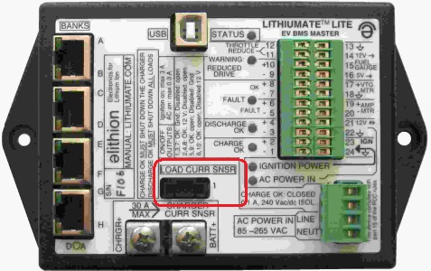
However, if later you discover that you installed it in the wrong direction, it may be easier to correct it through the configuration of the BMS, rather than turning the sensor around. Connect the sensor's connector to the BMS master's "Load Current Sensor" connector.
|
Lithiumate™ Lite Manual
User manual
User manual