Install cell boards
Install cell boards onto the cells and wire them
Li-Ion CELLS CAN CAUSE SERIOUS DAMAGE IF SHORT CIRCUITED!
DANGEROUS VOLTAGES: SHOCK DANGER!
Before working on cell boards, disconnect the battery from EVERYTHING else!
There are two ways that your Li-Ion pack can seriously harm you:
- Injury from catastrophic cell damage (typically due to a short circuit)
- Electrical shock
While we never heard of anyone being harmed by an electrical shock from an EV battery pack (anything more that an angry annoyance),
we have seen injuries and permanent bodily damage that resulted from a short circuit during assembly:
burned off skin, a permanent groove around a finger where a wedding ring used to be.
While working on a battery,:
- Prevent a short from occurring:
- Work in peace and quiet: distraction is the main reason that Li-Ion battery accidents occur
- Cover the battery with insulating panels of cloth, leaving only the part you're working on exposed (the way surgeons do)
- Bus bars, tools, fasteners and any other metal parts, should be either in use and in your hand, or on the table, away from the cell terminals;
if a metal part is placed at the same level or above the cell terminals,
gravity will always find a way to make it fall on the cells and short them out
- Wrap tools with electrical tape, leaving the minimum possible amount of exposed metal
- Remove your watch and rings
- Do not use metal calipers or straight edges to measure cells: use wood or plastic measuring devices.
- Reduce the total voltage:
- Install a mid-pack safety disconnect, and unplug it
- Disconnect batteries from each other
- In a single, long series string, temporarily remove bus bars between sections of the battery pack that are handled by separate banks
- Prevent a complete current path from forming:
- Disconnect the battery from everything else: that way, even if you touch one exposed terminal, you will not get shocked
- The battery must be completely isolated from earth ground: that way, even after it is connected to the load, even if you touch one exposed terminal, you will not get shocked
- If your right hand is doing the work, keep your left hand away from the terminals
- Should an event occur anyway, protect yourself from it:
- Wear safety glasses: a short circuit will turn the shorting object into plasma and blast its remains towards your face
- Have a plan for rushing a battery outdoors within 15 seconds from an event, before cells start exploding
A cell board WILL be damaged if you do any of these common mistakes.
A DAMAGED CELL BOARD MAY DRAIN ITS CELL!
|
Now that you have read how not to blow up yourself, the battery or the cell boards, you are ready to install the cell boards.
|
|
If you haven't done so already, install a safety disconnect.
A safety disconnect:
- Will give the EV driver an emergency way of shutting down the EV in case of trouble
- Will give Emergency Personnel, who are extricating a driver from an EV, a way of ensuring their own safety
- Once unplugged, will partially protect you when working on the battery pack
- Once unplugged, will reduce the chance for damage to the battery while you are working on the battery pack
- Once unplugged, will prevent cell boards from completing the circuit and blowing up
Ideally, a safety disconnect must be mid-pack (splitting the pack in 2), as that it where it does the best job at reducing the danger.
Ideally, it should be easy for the driver to open the safety disconnect while in the seat.
The safety disconnect can be a "Big Red Button" that is pushed to disconnect the pack.
Or, it could be an "Anderson" plug with a loop of wire, which completes the battery connection.
Or, it could be the simply a set of "Anderson" connectors, one on the battery and one on the cable to the rest of the vehicle.
Before working on a cell board, DISCONNECT THE SAFETY DISCONNECT, OR YOU WILL BLOW UP CELL BOARDS.
Note: a safety disconnect may not be placed within a bank. End a bank before the safety disconnect, and start the next bank after the safety disconnect.
Complete the power circuit: connect all the cells together, with straps, cables, bus bars or welding, as appropriate.
Divide the battery into banks: see the battery planning page.
- Identify a bank of cells: see the battery planning page
- Prepare a Cell Board for each cell in series in that bank
- Prepare 1 Positive End Cell Board for the most positive cell in the bank
- Prepare 1 Negative End Cell Board for the most negative cell in the bank
- Prepare n-2 mid-bank end Cell Boards for the the rest of the cell in the bank, where n is the number of cells in series in the bank
- Orient the Cell Board properly DO NOT CONNECT BACKWARDS!
- The ring terminal that is mounted directly to the Cell Board (labeled 'B-' on the PCB) goes to the negative terminal
- The ring terminal that is mounted on a red wire (labeled 'B+' on the PCB) goes to the positive terminal
- The electronic components go towards the cell, the LED towards you
- Place a Cell Board on the negative terminal of its cell
- Remove the bolt from the cell's negative terminal, keeping the power connection in place
- Place the 'B-' ring terminal (mounted directly to the Cell Board) on top of the power connection on the negative terminal
- Put the bolt back in and secure it
- Connect the Cell Board to the positive terminal
- Touch that terminal with the 'B+' ring terminal (mounted on the red wire)
- The LED will blink twice, repeated a total of 3 times
- If the LED doesn't blink when first connected, DISCONNECT THE CELL BOARD IMMEDIATELY
- If you installed the board backwards and removed it immediately, once connected properly it may appear to work correctly; however, it may be damaged and drain its cell
- Test a Cell Board with a current meter in series with one of its power terminals; after the blinking stops there should be no measurable current drain
- If the Cell Board draws measurable current after the blinking stops, or it it reports the wrong voltage, the Cell Board is damaged: replace it
- If the Cell Board was connected properly, and yet the LED doesn't blink, please see the cell troubleshooting page
- Remove the bolt from a cell's positive terminal, keeping the power connection in place
- Place the 'B+' ring terminal (mounted on the red wire) on top of the power connection on the positive terminal
- Put the bolt back in and secure it
- Repeat with the other cells in a bank
|
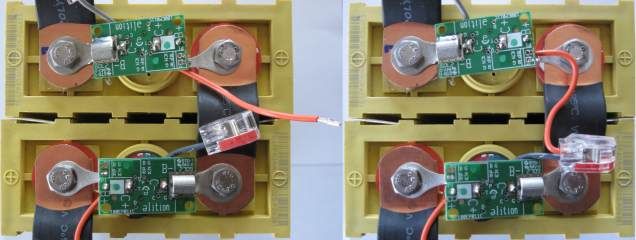
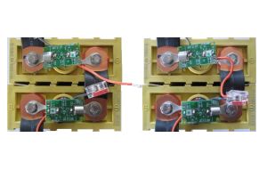
In between each pair of adjacent Cell Boards, the orange wire from the most negative of the 2 Cell Boards
is connected to the splice at the end of the gray wire from the most positive of the 2 Cell Boards.
- Point the gray wire towards the negative terminal of the cell
- Route the orange wire along the power bus bar between cells, and then to the gray wire in the adjacent Cell Board
- If the orange wire is too long, cut it shorter, so that it ends at the splice on the gray wire
- Strip the end of the orange wire 0.4" (1 cm)
- Insert the orange wire in an open slot in the splice at the end of the gray wire, push all the way in
- If required, secure the orange wire in place (use wire ties; do not twist it around the red wire or the bus bar)
In particularly noisy installations, you may need to use shielded cable.
Before using this solution, first follow the noise abatement procedures, which usually are sufficient to eliminate problems due to noise pick-up, without the need for shielded cable
|
Cut and strip orange wire (left)
and insert in splice (right).
|
Repeat with the remaining banks