AC installation
Connecting the Lithiumate Lite master to the AC power
NOTE: the input power connection depends on the revision level of the BMS master: Rev C uses pins 1 and 4, Rev F uses pins 3 and 4.
User supplied required parts:
- 3-conductor cable that is UL or CSA or CE rated, and that is rated for the AC voltage and for the charger's input current
- AC power inlet
- Plug for the charger's AC power input
- Fuse rated for 1 A and the AC voltage and for the charger's input current (2 fuses for 220 Vac split-phase operation)
- Fuse holder for the above fuse(s)
Route that cable:
- From the vehicle's AC power inlet
- To a fuse holder with a fuse that is rated for 1 A and the AC voltage and for the charger's input current (2 fuses for 220 Vac split-phase operation)
- To the master AC power plug
Connect the cable to the vehicle's AC power inlet:
- Black (or brown) to the Hot (or Line 1)
- White (or blue) to the Neutral (or Line 2)
- (Note that the ground wire (green or yellow-green) is not used by the BMS master.)
Connect the cable to the fuse holder:
- Cut the black (or brown) wire in two and wire at either end of the fuse
- For 220 Vac split-phase operation), cut the white (or blue) wire in two and wire at either end of the other fuse
|
Connect the the AC power to the master:
- Unplug the 4-screw green terminal block from the master (the screw numbers, 1 to 4, are shown on the master's label)
- Rev F master:
- Strip the black (or brown) wire; connect to screw # 3 of the green connector
- Strip the white (or blue) wire; connect to screw # 4 of the green connector
- Note that the two wires go to the two positions in the green terminal block closest to the outside edge of the box
- Plug the 4-screw green terminal block back into the master
- Note that the black (or brown) wire goes to the position labeled "L" (for "line"), and the white (or blue) wire goes to the position labeled "N" (for "neutral")
Rev C master:
- Strip the black (or brown) wire; connect to screw # 4 of the green connector
- Strip the white (or blue) wire; connect to screw # 1 of the green connector
- Note that the two wires go to the two outside positions in the green terminal block
Plug the 4-screw green terminal block back into the master
Note that the black (or brown) wire goes to the position labeled "L" (for "line"), and the white (or blue) wire goes to the position labeled "N" (for "neutral")
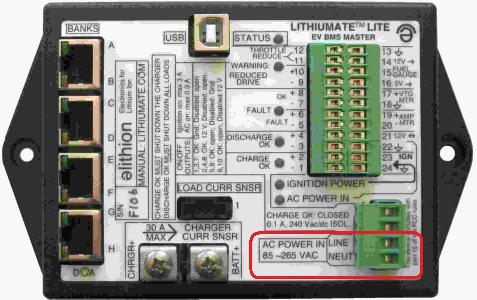
Connection location or rev F master. NOTE: rev C master is uses pins 1 and 4 instead!
| |
|
Connect the AC power to the AC source:
- Earth (green / yellow):
- Run a line from the Earth contact of the AC inlet to the chassis
- Neutral (blue or white):
- Run a line from the the Neutral contact of the AC inlet to the AC inputs of the BMS controller and the 12 V charger
- Hot (brown or black):
- Run a line from the the Hot (Line) contact of the AC inlet, to a 1 A fuse rated 250 Vac
- Run a line from the other end of the fuse to the AC inputs of the BMS controller and the 12 V charger
|
Lithiumate Lite master AC power connections
|
|

© 2008~2025 Elithion™, Inc.. All rights reserved.
The Elithion brand and the 'ə' (upside down 'e') logo are Trademarks of Elithion Inc.
Page published on: May 07 2024.
Installation manual