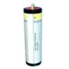
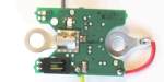
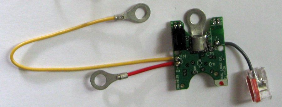
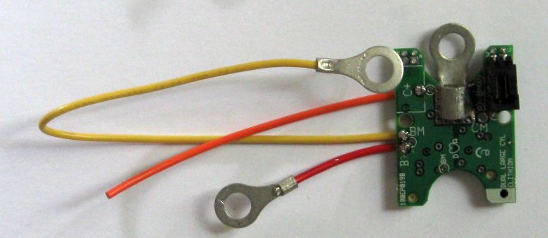
Cell board, large cylindrical, two cell Notice: This product has been discontinued and is no longer available | |
Each of these cell boards handles two large cylindrical cells.
- Matched to industry standard sizes
- Mounted on the end terminals of two, side-by-side, adjacent cells
- Reliable mechanical mounting and direct electrical connection
- One Cell Board per 2 cells (or 2 sets of multiple cells in parallel)
- Highest flexibility, as they may be used with many cell arrangements
- Flat shape: doesn't extend past current carrying bolts
- A single voltage sense wire is connected to the terminals on the opposite end of the cells
- A single communication wire is used between adjacent cell boards in a bank
- These cell boards require a BMS master to form a complete BMS
|
|
|
These cell boards can be used with a variety of large cylindrical cells. They are available in 2 sizes, to accommodate various cell sizes.
For more information, see the installation instructions.
Installation is straightforward:
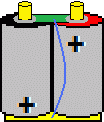
- Mount cells side-by-side, with alternating polarity
- Install a cell board on the terminals of 2 adjacent cells, on the side where they are not connected together
- Connect the ring terminal on a long wire to the terminals at the other end of the cells
- Connect adjacent cell boards with a communications wire
|
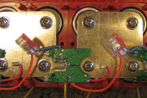 
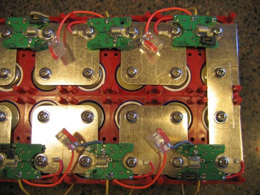
Cell boards mounted on a 24S2P battery of Headway 38120 cells Travis Gintz).
|
|
These standard Cell Boards are compatible with most large cylindrical cells available on the market today, including:
|
|
|
General specifications (for detailed specifications, please see the Lithiumate™ Manual).
|
| Symbol
| Item
| Conditions
| Min
| Nom
| Max
| Units
|
| Vrange
| Cell voltage sensing range
| -
| 2.09
| -
| 4.54
| V
|
| Vaccur
| Cell voltage sensing accuracy
| Within Vrange
| -
| ±10
| ±15
| mV
|
| Isply
| Cell load current
| Stand-by
| -
| -
| 2.0
| µA
|
Active,
1-reading / sec
| -
| 1.5
| 2.0
| mA
|
| Balancing
| -
| 200
| -
| mA
|
| VISOL
| Isolation voltage
| End cell boards
Between battery & low voltage
| -
| 2500
| -
| V
|
|
|
Common specifications:
|
| Item
| Nom
|
| PCB Width
| 1.2" / 30.5 mm
|
| PCB Length
| 1.6" / 40.6 mm
|
| PCB thickness
| 0.062" / 1.6 mm
|
| Overall height, no connector
| 0.3" / 7.5 mm
|
| Overall height, w/ right angle connector
| 0.47" / 12 mm
|
| Terminal material
| Plated copper
|
| Wire gauge
| 18 AWG
|
|
|
Specifications particular to each model:
|
| P/N
| Center-to-center spacing between adjacent cells
| Cell length
| Bolt size
| Ring term
|
| Min 'D'
| Max 'D'
| Min 'L'
| Max 'L'
| ID
| OD
|
| 1LC0040x
| 1.5" / 38 mm
| 3.14" / 80 mm
| 4.72" / 120 mm
| 6.30" / 160 mm
| 1/4" / M6
| 0.25" / 6.3 mm
| 0.48" / 12 mm
|
| 1LC0060x
| 2.36" / 60 mm
| 5.12" / 130 mm
| 9.13" / 232 mm
| 1/2" / M12
| 0.515" / 13 mm
| 1.25" / 31.7 mm
|
|
Each bank requires a positive cell board on its most positive cell, a negative cell board on its most negative cell, and mid-bank cell boards in the remaining cells.
(The automatic quote form will select the correct number of each type of board for you.)
Right angle connectors are standard on full bank and end boards.
Versions with straight connectors or without connectors are available with quick turnaround
- With right angle connectors - requires a slight extra mounting space beyond the cell bolts
- With straight connectors - requires significant extra mounting space beyond the cell bolts
- Without connectors (cables to the BMS controller are soldered directly to the cell board) - requires no extra space beyond the cell bolts
Part number: 1LC0040M:
- 1 = Cell Board
- LC = Large Cylindrical
- 0040 = nominal center-to-center spacing of cell terminals, in mm (available: 40, 60)
- M = mid bank (available:M = mid-bank; P = positive end; N = negative end)
|
Note: (*)
- For N cells, where N is even, you need n/2-2 "mid-bank" cell boards, and only 1/2 of the negative board is used
- For N cells, where N is odd, you need (n+1)/2-2 "mid-bank" cell boards
|
Number of cells
in the bank
| Cell boards
|
| Mid-bank*
| Positive
| Negative
|
| 3
| 0
| 1
| 1*
|
| 4
| 0
| 1
| 1
|
| 5
| 1
| 1
| 1*
|
| 6
| 1
| 1
| 1
|
| 7
| 2
| 1
| 1*
|
| 8
| 2
| 1
| 1
|
| 9
| 3
| 1
| 1*
|
| 10
| 3
| 1
| 1
|
| 11
| 4
| 1
| 1*
|
| 12
| 4
| 1
| 1
|
| 13
| 5
| 1
| 1*
|
| 14
| 5
| 1
| 1
|
| 15
| 6
| 1
| 1*
|
| 16
| 6
| 1
| 1
|
|
|
Not stocked, made to order.
|
|
To order, please see the Lithiumate BMS ordering form.