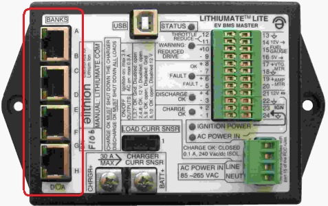
Bank connection
Connect the BMS master to the banks
Because two bank connections share the same cable between the BMS master and the banks,
you need to put some thought on which banks will be paired up.
This will be based on convenience, due to relative physical locations of the banks.
Also, for your own sake, it would be nice if the the relationship between the order in which you numbered the banks,
and the letter of the banks on the BMS master, would be easy to remember.
(The BMS doesn't care: it can handle any way you connect the banks to it.)
It doesn't matter to the BMS if a bank remains unpaired, and uses a cable all for itself.
It doesn't matter to the BMS which letter goes to which bank,
but we recommend that you have 'A' for the most positive bank.
Note that each pair of banks has a "green" bank and a "yellow" bank:
the green bank uses a green LED and green heat shrink at the end of the small cables to the end cell boards;
while the yellow bank uses a yellow LED and yellow heat shrink.
|
Try to divide the battery banks into pairs, in such way to minimize the number of cables from the BMS master.
If you have 4 banks, you could have a cable for each bank and be done with it.
Or, you could try to be neat and do it with just 2 cables, one for each pair of banks.
It doesn't matter to the BMS how banks are paired, but we recommend that you pair banks that are electrically contiguous to each other:
the most positive bank and the one connected to it (more negative) as one pair, the next two as the next pair, etc.
For each pair of banks, install a bank breakout close to those banks.
For each bank in the pair, route the green cables to one bank and the yellow wires to the other bank.
It doesn't matter to the BMS which color goes to which bank, but we recommend that you connect the green cables to the most positive of the two.
|
Connection location.
|
Both of the connectors at the ends of the cables of a given color have 2 pins, but they are physically different (their release tabs are different).
For each bank, connect the connector with the wide release tab to the negative end cell board, and the connector with the narrow release tab to the positive end cell board.
For each pair of banks, use a shielded modular RJ45 connector to connect the breakout to the BMS master.
It doesn't matter to the BMS which cable goes where, but we recommend that the most positive pair of banks goes to connector "A & B", the next one (more negative) to connector "C and D", etc.