Vinci EV BMS, distributed topology Description, configuration and ordering | |
|
A cell module is mounted on each cell.
The BMS uses a Master/Slave topology, consisting of a number of modules;
communication among all modules is through a 5-wire bus.
Cells are divided into banks of up to 25 cells;
slaves are connected to a bank of cells through 2-wire cables.
The BMS consists of:
|
Item
|
Info
|
Function
|
Qty
|
| VinciBus Battery Master
| Info
| Manage the battery
| 1
|
| VinciBus Distributed Slaves
| Info
| Interface to a bank of cells boards
| 1+
|
| Application module
| Info
| Add Traction Pack functions
| 1
|
| Contactor set
| Info
| Precharge, disconnect the battery
| 1
|
| Current sensors
| Info
| Sense the battery current
| 0~2
|
| Prismatic cell modules
| Info
| Connection to prismatic cells
| 1/cell
|
| Small cylindrical or pouch cell boards
| Info
| Connection to pouch cells
| 1/cell
|
| Bank wiring
| Info
| Connection to the 2 cell modules at the end of the bank
| 1 set
|
| VinciBus wiring components
| Info
| Between modules
| 2+
|
| Communications adapters
| Info
| To a computer for monitoring
| (1)
|
|
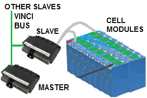
Distributed topology
|
For spare parts, please contact us